
Slide rail type multi-level vertical wind power generation device

A technology of wind power generation device and slide rail, which is applied in wind power generation, wind power generator, wind power generator at right angles to the wind direction, etc. It can solve the problems of difficult installation, large centrifugal force, easy to be blown over, etc., so as to increase the weight of the device, occupy Small ground area, enhanced effect of wind resistance

Pending Publication Date: 2020-09-25
四川中能驭风新能源有限公司
View PDF0 Cites 3 Cited by
  • Summary
  • Abstract
  • Description
  • Claims
  • Application Information

AI Technical Summary

Problems solved by technology

When the height of the blade increases, the wind resistance of the blade becomes worse, and it is necessary to increase the shaft size of the blade and strengthen the support of the shaft; in this way, the weight and manufacturing cost of the fan blade are correspondingly increased, and the requirements for the support shaft are also increased. Increased, the installation is also more difficult, moreover, when the multi-layer blades rotate at the same time, the centrifugal force generated is relatively large, which is easy to cause damage to the impeller shaft
From the above, it can be seen that under the condition of ensuring sufficient wind receiving area, how to ensure that the vertical blades of the vertical axis wind turbine are stably arranged on the vertical axis is a challenge faced by the design, manufacture and installation of the blades of the large power vertical axis wind turbine. There is still no better solution to the key problem, and especially on some islands, due to the strong wind, the whole device is underweight and easily blown over, causing unnecessary losses

Method used


Image

  • Slide rail type multi-level vertical wind power generation device
  • Slide rail type multi-level vertical wind power generation device
  • Slide rail type multi-level vertical wind power generation device

Examples


Embodiment 1

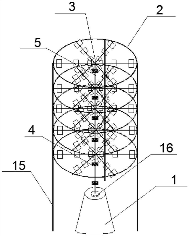
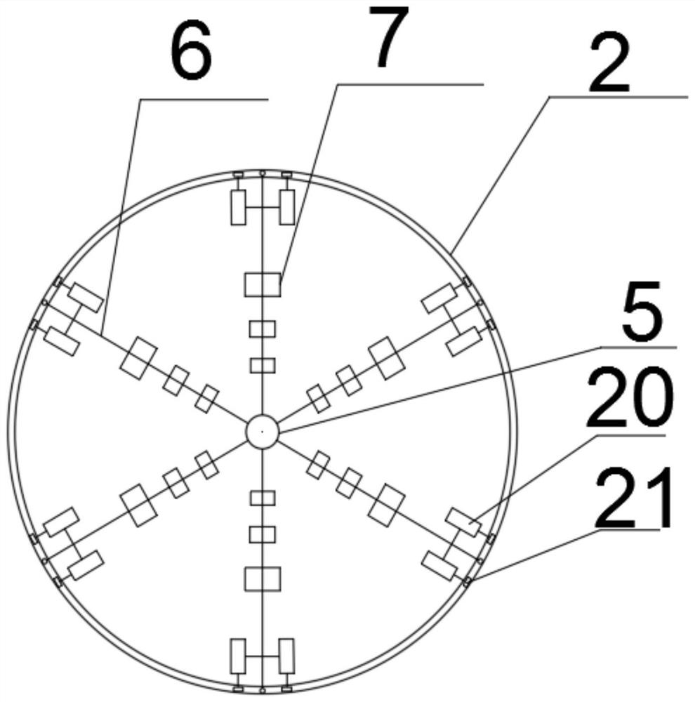
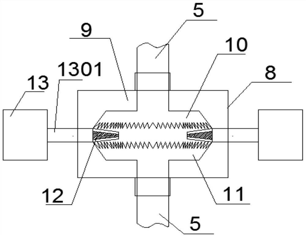
[0049] Specifically, such as figure 1 , as shown in 2, the power generation device of the present invention mainly includes a base 1, an annular support 2 and multiple sets of generating sets 3, the base 1 and multiple sets of generating sets 3 are arranged in the annular support 2, and the bottommost generating set 3. The base 1 is connected to the base 1 through the bearing 16. The base 1 is used to stabilize the stability of each generating set 3. Multiple sets of the generating sets 3 are sequentially connected in series through the transmission box 4 from bottom to top, so that the overall footprint is small and the power generation efficiency is high. The generating set 3 includes a plurality of support arms 6, impeller shafts 5 and blades 7 fixed on the support arms 6, one end of the plurality of support arms 6 is fixedly connected to the impeller shaft 5, and is radially distributed in the circumferential direction of the impeller shaft 5 , each support arm 6 is provid...

Embodiment 2

[0051] Specifically, such as Figure 9 As shown, a bracket 22 is welded or bolted between any adjacent two support arms 6, the bracket 22 can be set in an arc shape, and a plurality of auxiliary generators 20 are evenly distributed in a fan shape on the bracket 22, and the auxiliary generators 20 are fixed by bolts On the support 22, the rotor of the auxiliary generator 20 is radially along the annular support 2 and towards the annular support 2, which further increases the weight of the whole device and makes the stability and wind resistance of the device better, such as Figure 4-7 , shown in 10 and 11, the top surface of the annular support 2 is provided with an annular groove track 19, and the circular block 21 at the end of the guide wheel 14 and the rotor is located in the groove track 19, so that in the sliding process, the guide wheel 14 and the Circular block 21 is not easy to drop from ring support 2, is smeared with polytetrafluoroethylene on groove track 19 surfac...

Embodiment 3

[0053] Specifically, such as figure 1 As shown, the total number of layers of the generator set 3 is at least two layers. Since the rotation direction of any two adjacent layers of the generator set 3 is opposite, the wind blowing in from any direction can be collected, further improving the power generation of the generator set 3. Adaptability under various working conditions, and at the same time improve the collection and conversion efficiency of wind energy to electric energy, achieve the purpose of maximizing the use of wind energy to increase production capacity, and realize the increase of power generation current. The direction is opposite, so that the rotation directions of the adjacent two-layer generator sets 3 are opposite, which can offset the centrifugal force generated by the mutual rotation of the two-layer generator sets 3 on the impeller shaft 5, thereby protecting the impeller shaft 5 from damage and prolonging the service life of the power generation device....


PUM


Abstract

The invention discloses a slide rail type multi-level vertical wind power generation device. The slide rail type multi-level vertical wind power generation device comprises a base, annular supports and multiple sets of power generation units. The base and the multiple sets of power generation units are arranged in the annular supports. The multiple sets of power generation units are sequentially connected in series from bottom to top through transmission boxes. Each power generation unit comprises multiple support arms, an impeller shaft and vanes fixed to the support arms. The multiple support arms are distributed in the circumferential direction of the corresponding impeller shaft in a radial manner. A guide wheel is arranged at the end, away from the corresponding impeller shaft, of each support arm and extends horizontally to the top face of the corresponding annular support. Each support arm can slide along the corresponding annular support with the corresponding impeller shaft asthe circle center. Subsidiary electric generators are fixed to two sides of each support arm. Rotors of the subsidiary electric generators are in the same direction with the radial direction of the corresponding annular support. Circular blocks are fixed to ends of the rotors. The circular blocks are in sliding connection with the top faces of the annular supports. Support rods extending to the ground are fixed to the outer side faces of the annular supports. The power generation unit located at the very bottom is connected with the base through a bearing. The slide rail type multi-level vertical wind power generation device has better stability and wind resistance; and in the meantime, the device has the function of multi-level power generation, and power generation efficiency is improved.

Description

technical field [0001] The invention relates to the technical field of wind power generation, in particular to a sliding rail type multi-stage vertical wind power generation device. Background technique [0002] The available resources on the earth are decreasing day by day. Today, with the increasing awareness of environmental protection, the utilization and development of renewable energy has been paid more and more attention by various countries due to the characteristics of clean energy and low greenhouse gas emissions. Among them, solar power generation and wind power generation are the most important. [0003] Wind turbines are distinguished by the direction of the impeller rotation axis, and there are two types: horizontal axis type and vertical axis type. At present, in the domestic and foreign markets, the horizontal axis wind turbine is still the mainstream form. However, horizontal axis wind turbines have significant disadvantages. For example, the horizontal a...

Claims


Application Information

Patent Timeline
Patent Type & Authority Applications(China)
IPC IPC(8): F03D9/25F03D3/02F03D3/06F03D5/04F03D15/00F03D80/00
CPCF03D9/25F03D3/005F03D3/02F03D3/064F03D3/061F03D5/04F03D15/00F03D80/00Y02E10/70Y02E10/74
Inventor 高宇
Owner 四川中能驭风新能源有限公司
Learn More