
Pipeline placing device for building engineering

A construction engineering and pipeline technology, applied in the field of pipeline placement devices for construction engineering, can solve problems such as damage to workers and collapse, and achieve the effect of convenient use

Inactive Publication Date: 2020-09-25
蔡方
View PDF0 Cites 1 Cited by
  • Summary
  • Abstract
  • Description
  • Claims
  • Application Information

AI Technical Summary

Problems solved by technology

[0002] Various pipes are used in construction projects, such as water pipes, waste pipes, gas pipes, etc. The pipes used in the pipeline installation process need to be manually unloaded, but for the convenience of transportation, the pipes are all stacked. Neatly, once one of them is extracted, it may cause a collapse and damage the staff on site

Method used


Image

  • Pipeline placing device for building engineering
  • Pipeline placing device for building engineering
  • Pipeline placing device for building engineering

Examples


Embodiment 1

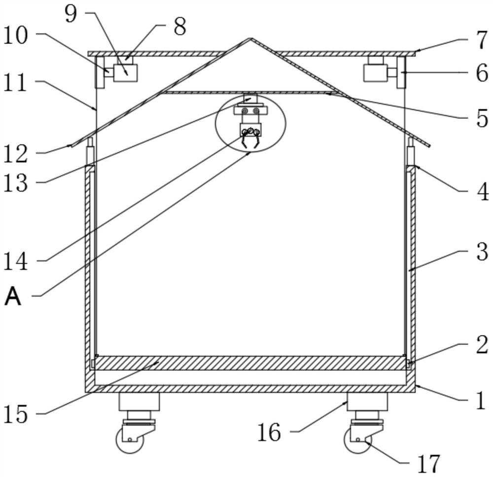
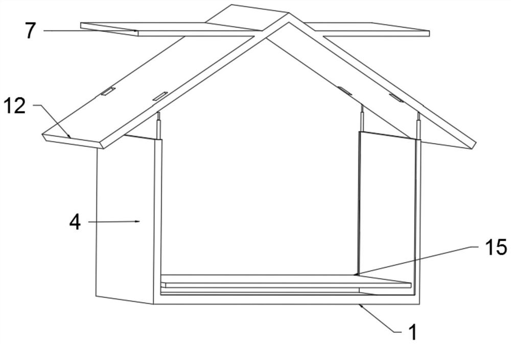
[0020] see Figure 1-4 , a pipeline placement device for construction engineering, comprising a base 1, a placement plate 15 and a pipeline removal structure, a placement plate 15 is arranged above the base 1, a pipeline removal structure is arranged above the placement plate 15, and the pipeline The unloading structure includes a single pipe unloading mechanism and an integral unloading mechanism, a side support bar 4 is arranged on the upper side of the base 1, and a top slant plate 12 is provided at the end of the side support bar 4, and the top slant A horizontal plate 1 is arranged inside the middle of the plate 12, a horizontal plate 2 7 is arranged on the outside of the top slant plate, a single pipe removal mechanism is arranged under the horizontal plate 1 5, and a horizontal plate 2 7 is arranged below the sides An integral removal mechanism, the end of the overall removal mechanism is provided with a traction rope 11, the side of the placement plate 15 is provided w...

Embodiment 2

[0027] Compared with Embodiment 1, the improvement of this embodiment lies in that: a telescopic rod 16 is provided under the base 1 , and a universal wheel 17 is provided at the end of the telescopic rod 16 . In the transportation process, universal wheels 17 can be used to move and transport the whole box body, which is convenient and fast.

[0028] The working principle of the present invention is: place the pipeline on the placement plate 15, and when it needs to be extracted for utilization, a single pipeline is needed, and the horizontal motor 18 is used to drive the horizontal ball screw 19, so that the fixed sleeve 20 moves laterally, so that the clamping structure 14 Arrive at a suitable position, then according to the rotation of gear one 30, drive the rotation of gear two 29 and gear three 25, so that the clamping block 27 expands, and the pipe is approached, and then the gear two 29 and gear three 25 are reversely rotated to clamp At the same time, the suction cup ...


PUM


Abstract

The invention discloses a pipeline placing device for building engineering. The pipeline placing device comprises a base, a placing plate and a pipeline disassembling structure. The pipeline disassembling structure comprises a single pipeline disassembling mechanism and an overall disassembling mechanism. The single pipeline disassembling mechanism comprises an elevating mechanism, a third gear, asecond gear, a first gear, a clamping block, a fixing shaft, a sucker, a transverse motor, a transverse ball screw, a fixing sleeve, a tail device and a tail supporting base. The overall disassembling mechanism comprises a motor, a rotating shaft, a placing and releasing roller and a motor supporting base. According to the pipeline placing device, by arranging the single pipeline disassembling structure and the overall disassembling structure, different application occasions of multiple pipelines can be achieved, the situation that when the pipelines are taken out, the pipelines collapse andhurt personnel is avoided, when the overall disassembling structure acts, the pipelines topple over, thus the dispersing effect is achieved, and use is convenient.

Description

technical field [0001] The invention relates to a placement device, in particular to a pipe placement device for construction engineering. Background technique [0002] Various pipes are used in construction projects, such as water pipes, waste pipes, gas pipes, etc. The pipes used in the pipeline installation process need to be manually unloaded, but for the convenience of transportation, the pipes are all stacked. Neatly, once one of them is extracted, it may cause a collapse and damage the staff on site. Contents of the invention [0003] The object of the present invention is to provide a pipe placement device for construction engineering, so as to solve the problems raised in the above-mentioned background technology. [0004] To achieve the above object, the present invention provides the following technical solutions: [0005] A pipe placement device for construction engineering, comprising a base, a placement plate and a pipe removal structure, a placement plate ...

Claims


Application Information

Patent Timeline
Patent Type & Authority Applications(China)
IPC IPC(8): B65D25/24B65D25/02B65D85/20B65D25/52
CPCB65D25/02B65D25/24B65D25/52B65D85/20
Inventor 蔡方
Owner 蔡方
Learn More