
Topology control system and control method for dynamic network

A dynamic network and topology control technology, applied in the field of communication, can solve the problems of network data fusion and unified scheduling, reduce network robustness and anti-interference ability, adverse network load balancing and scalability, etc., to improve network cooperation. capacity, improve throughput and stability, reduce the effect of mutual interference

Active Publication Date: 2021-09-03
XIDIAN UNIV
View PDF5 Cites 0 Cited by
  • Summary
  • Abstract
  • Description
  • Claims
  • Application Information

AI Technical Summary

Problems solved by technology

For a topology control system with a centralized architecture, the central node of the network needs to run a highly complex algorithm, and is almost entirely responsible for the maintenance and update of the entire network, which causes the center of the network to bear a huge load, and With the continuous expansion of the network scale, the computing load and communication load of the central node are increasing rapidly, which is not conducive to the load balancing and scalability of the network.
In addition, once the central node encounters interference or damage, all nodes in the network will not be able to work normally, thus causing the paralysis of the entire network and reducing the robustness and anti-interference ability of the network
For the topology control system with distributed architecture, the network can achieve load balancing and has high robustness, but the nodes in the network work independently and cannot cooperate well and efficiently, which brings great challenges to the data fusion and unified scheduling of the network. big difficulty

Method used


Image

  • Topology control system and control method for dynamic network
  • Topology control system and control method for dynamic network
  • Topology control system and control method for dynamic network

Examples


Embodiment Construction

[0033] The embodiments of the present invention will be clearly and completely described below in conjunction with the accompanying drawings. Apparently, the described embodiments are part of the embodiments of the present invention, but not all of them. Based on the embodiments of the present invention, all other embodiments obtained by persons of ordinary skill in the art without making creative efforts belong to the protection scope of the present invention.

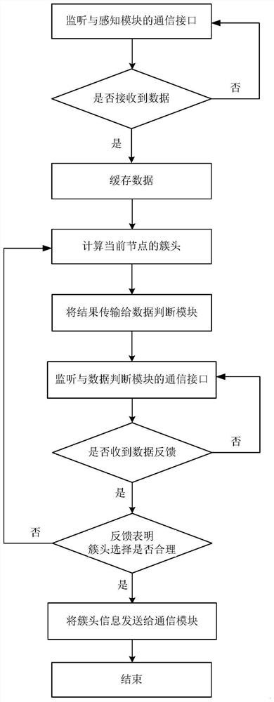
[0034] The invention mainly aims at the topology control problem of the dynamic network, and proposes a network topology control method suitable for mobile nodes and a corresponding network topology control system. The network topology control method and the network topology control system can adjust the communication relationship and topology structure between network nodes in real time according to the state of the nodes, while ensuring the network connectivity, use the power control of the nodes to save energy consu...


PUM


Abstract

The invention discloses a topology control system and a corresponding topology control method suitable for dynamic networks, which mainly solve the problem of performance degradation when the existing network topology control systems and methods are used in dynamic networks, including a perception module and a data processing module , a data judging module, a communication module and a central module. The sensing module, data judging module, and communication module are respectively connected to the data processing module by wire, and the communication module is connected to the central module wirelessly; the sensing module collects the data of surrounding nodes, transmits them to the data processing module for caching, and selects the cluster head of the current node according to the data. It is transmitted to the data judgment module; after the data judgment module checks that the cluster head is qualified, the communication module is responsible for wirelessly transmitting the cluster head information to the central module; the central module summarizes the data of all nodes in the network and transmits the result to the client. The invention can improve the stability of the dynamic network and can be used for topology control of the dynamic network.

Description

technical field [0001] The invention belongs to the technical field of communication, and further relates to a node topology control system and method, which can be used in a dynamic network formed by mobile nodes. Background technique [0002] The Ad-Hoc network is a network connection established by dozens or hundreds of nodes equipped with sensing devices, computing devices, and communication devices through wireless communication. It is a network that can quickly deploy applications without pre-establishing fixed infrastructure. system. In the Ad-Hoc network, nodes cooperate with each other, and each node selects neighbor nodes within its communication range to establish a connection, and forms a network that meets connectivity through network clustering, multi-hop transmission, and other means. [0003] For the Ad-Hoc network composed of nodes such as automobiles, ships, and drones, the high-speed movement of nodes may cause the connected nodes in the network to leave ...

Claims


Application Information

Patent Timeline
Patent Type & Authority Patents(China)
IPC IPC(8): H04W28/08H04L12/24H04W84/18H04L45/02
CPCH04W28/08H04L41/12H04W84/18H04L45/02H04L67/12H04L43/0811H04W40/32H04W40/08H04W40/24Y02D30/70H04L67/1042H04W24/02H04L45/123H04L45/46
Inventor 李长乐张云锋李文刚左沛昂亓玉腾杨柳颜
Owner XIDIAN UNIV
Learn More