Metal wet mold

A wet mold, metal technology, used in heat exchange equipment, fixed plate duct components, heat exchanger types, etc., can solve the problems of large space occupied by the water tank and poor heat dissipation effect, so as to increase the heat dissipation area, improve the cooling speed, and avoid the The effect of taking up more space

Inactive Publication Date: 2020-09-22
广州冰原环境技术有限公司
View PDF6 Cites 0 Cited by
  • Summary
  • Abstract
  • Description
  • Claims
  • Application Information

AI Technical Summary

Problems solved by technology

[0002] The metal wet mold is a cooling structure for cooling hot water in the water circulation mechanism. Generally, the cooling structure in the water circulation mechanism of the reactor is a water tank. The upper and lower parts of the reactor are respectively equipped with a water outlet and a water inlet. Between the water outlets, the hot water in the reaction kettle enters the water tank from the water inlet, and the hot water contacts the water tank to realize heat exchange, and the water tank dissipates heat to the surrounding air to cool down the hot water. The heat dissipation speed of the water tank is not as fast as the rising speed of the water temperature in the water tank, and the heat dissipation effect is poor. In order to improve the heat dissipation effect of the water tank, the volume of the water tank is usually increased to increase the heat dissipation area of ​​the water tank, which leads to the excessive space occupied by the water tank

Method used


Image

  • Metal wet mold
  • Metal wet mold
  • Metal wet mold

Examples


Embodiment Construction

[0019] The present invention will be further described below in conjunction with accompanying drawing:

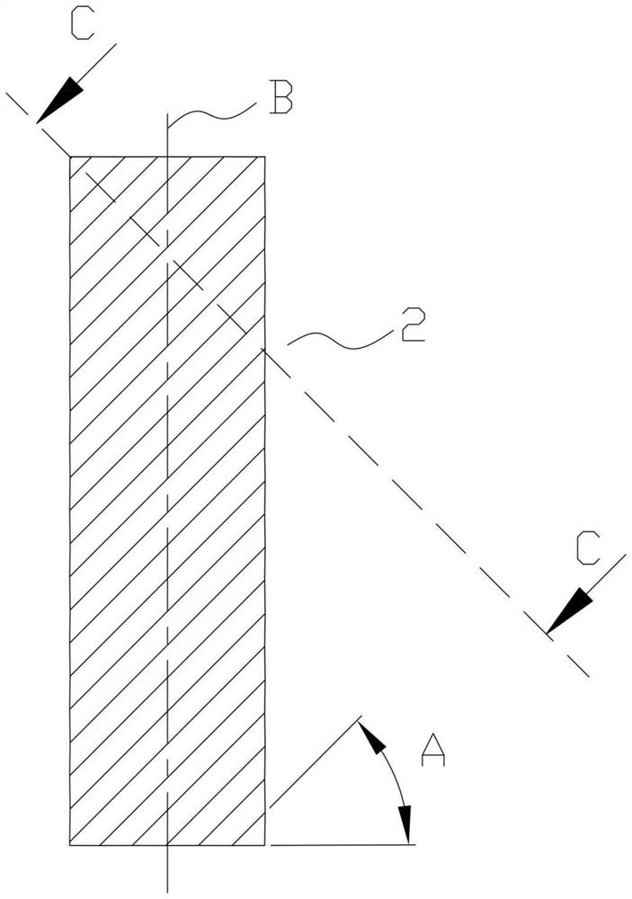
[0020] Please refer to Figure 1 to Figure 3 , a metal wet mold, comprising a frame 1, a plurality of corrugated fins 1 2 and a plurality of corrugated fins 2 3, the corrugated fins 1 2 and corrugated fins 2 3 are rectangular in shape, and the corrugated fins The length and width of heat sink 1 2 and pleated heat sink 2 3 are the same, and the pleated heat sink 1 2 and pleated heat sink 2 3 are all made of metal material to prolong the service life. The metal material is copper foil or stainless steel foil or aluminum foil The pleated heat sink 1 2 is provided with a pleated structure 1, and the pleated radiating fin 2 3 is provided with a pleated structure 2. Both the pleated structure 1 and the pleated structure 2 are set obliquely. When the first and second pleated structures are up, they can move obliquely downward while falling, which not only ensures that the hot wat...


PUM

PropertyMeasurementUnit
Bevel angleaaaaaaaaaa

Abstract

The invention provides a metal wet mold. The metal wet mold comprises a framework, a plurality of wrinkled heat-dissipation sheets I and a plurality of wrinkled heat-dissipation sheets II, wherein thewrinkled heat-dissipation sheets I are provided with wrinkled structures I; the wrinkled heat-dissipation sheets II are provided with wrinkled structures II; both the wrinkled structures I and the wrinkled structures II are arranged obliquely; the wrinkled heat-dissipation sheets I and the wrinkled heat-dissipation sheets II are arranged in the framework alternatively; and adjacent wrinkled structures I and wrinkled structures II are in a crossing state. Hot water flows into spaces between the wrinkled structures I and the wrinkled structures II from top to bottom, and comes into continuous contact with the wrinkled structure I and the wrinkled structure II in a falling process, so that the surface areas of the wrinkled structures I and the wrinkled structures II are increased compared with a planar structure; the heat-dissipation area is increased; and good hot water cooling effect is achieved. Gaps are formed between the wrinkled structures I and the wrinkled structures II, so thatsurrounding flowing air can pass through the gaps for taking the heat of the hot water, the wrinkled heat-dissipation sheets I and the wrinkled heat-dissipation sheets II away, and the cooling speed is increased.

Description

technical field [0001] The invention relates to the field of cooling structures, in particular to a metal wet mold for cooling hot water. Background technique [0002] The metal wet mold is a cooling structure for cooling hot water in the water circulation mechanism. Generally, the cooling structure in the water circulation mechanism of the reactor is a water tank. The upper and lower parts of the reactor are respectively equipped with a water outlet and a water inlet. Between the water outlets, the hot water in the reaction kettle enters the water tank from the water inlet, and the hot water contacts the water tank to realize heat exchange, and the water tank dissipates heat to the surrounding air to cool down the hot water. The heat dissipation speed of the water tank is not as fast as the rising speed of the water temperature in the water tank, and the heat dissipation effect is poor. In order to improve the heat dissipation effect of the water tank, the volume of the wat...

Claims


Application Information

Patent Timeline
IPC IPC(8): F28D9/04F28F3/04F28F21/00
CPCF28D9/0025F28D9/04F28F3/046F28F21/00
Inventor 李芳星
Owner 广州冰原环境技术有限公司
Why Eureka
Try Eureka