


Quick Research
Generate reliable direction feasibility study reports for your R&D in just a few steps.

Technical Q&A
Discover and master advanced knowledge NOW. Basics, ideas, possibilities, all at once.

Find Solutions
As an expert in R&D theories, this can generate solutions to your technical problems instantly.

Evaluate Feasibility
Analyze your overall solution with one click, know your potential R&D risks in advance.

Monitor Landscape
Get weekly tech updates, stay abreast of the latest tech innovations and key insights.
VFL (vertical flow labyrinth) water flow structure, device, system and method for sewage treatment
A technology for sewage treatment and sewage treatment tank, which is applied in biological treatment devices, biological water/sewage treatment, water/sludge/sewage treatment, etc. It can solve the problem of high energy consumption, strong water and biological corrosion, and increase equipment maintenance costs and other problems, to avoid blockage, ensure the treatment effect, and ensure the effect of the effect
- Summary
- Abstract
- Description
- Claims
- Application Information
AI Technical Summary
Problems solved by technology
Method used
Image

Examples
Embodiment 1
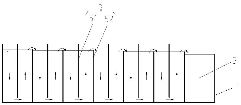
[0046] Please refer to figure 1 As shown, a VFL vertical flow labyrinth water flow structure for sewage treatment, the VFL vertical flow labyrinth water flow structure is applied in the biochemical sewage treatment device, in this embodiment, the VFL vertical flow labyrinth water flow structure includes a water flow structure located in the sewage treatment pool 1 The inner diversion wall structure 2, the lower end of the diversion wall structure 2 is fixedly connected with the bottom of the sewage treatment tank 1. The diversion wall structure 2 is used to divide the sewage treatment pool 1 to form an anaerobic zone, anoxic zone, and aerobic zone 3 connected in sequence, and a diversion channel 4 is provided between the front end of the anaerobic zone and the front end of the aerobic zone 3 .
[0047] Such as figure 1 As shown, the sewage diversion channel 4 is provided with a sewage diversion structure 5, the sewage diversion structure 5 includes a plurality of first deflec...
Embodiment 2
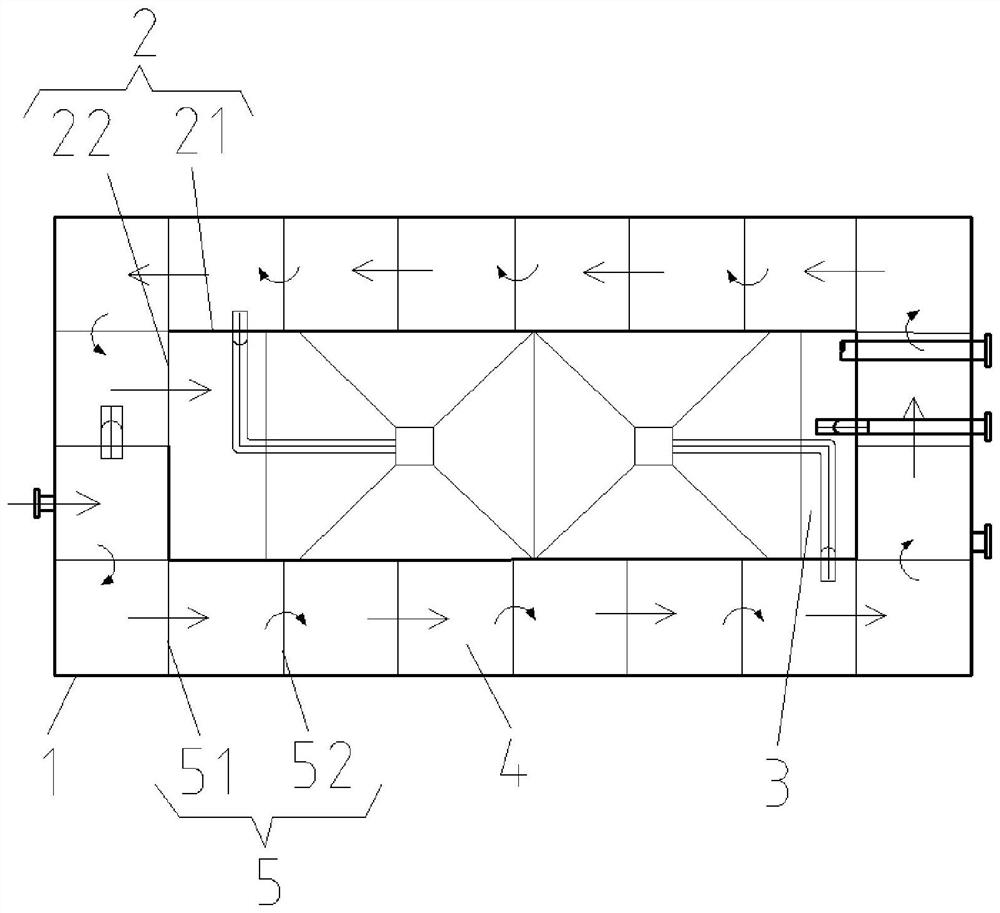
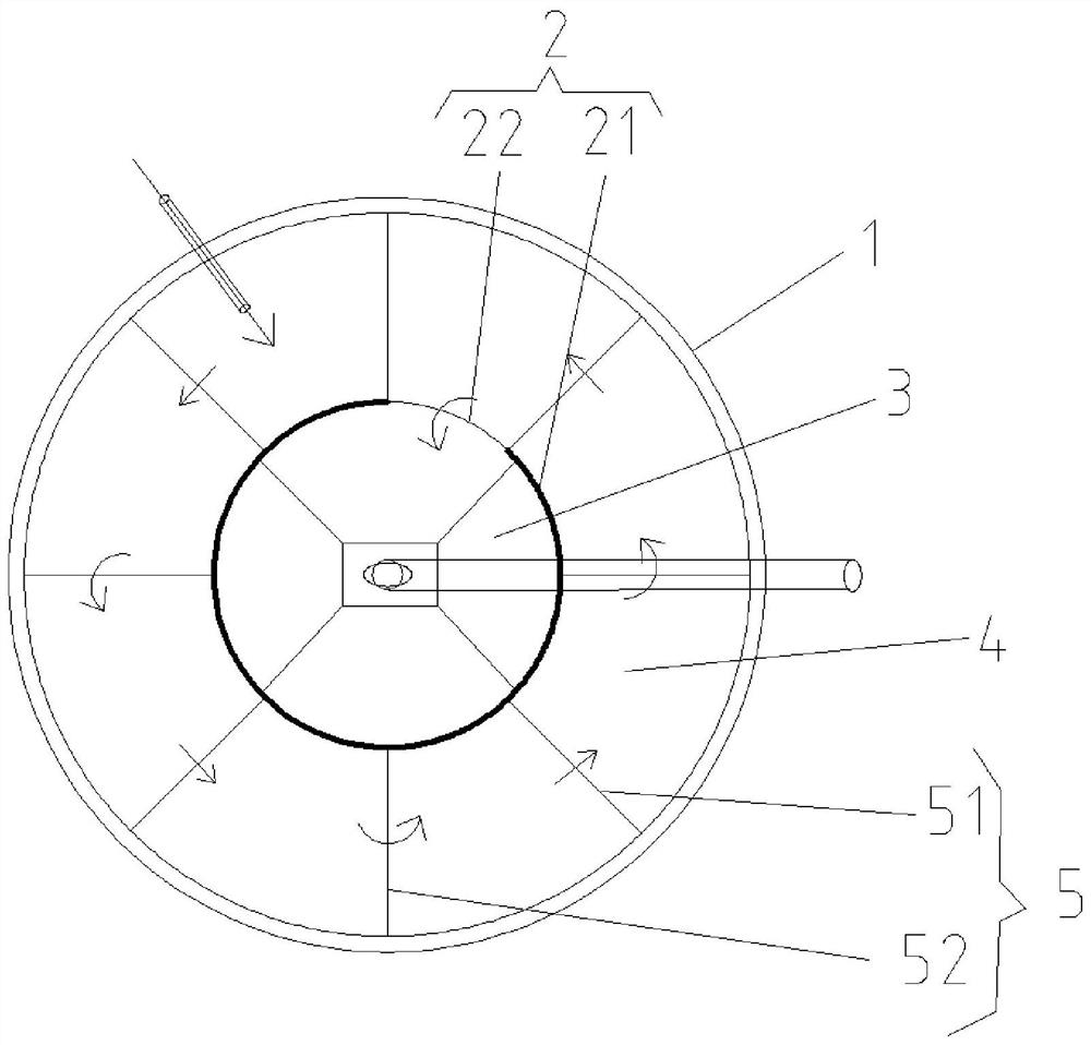
[0059] Generally speaking, the shapes of sewage treatment tanks 1 of biochemical sewage treatment devices of different enterprises, different geographical environments, and different sewage treatment requirements are different. In order to make the diversion wall structure 2 suitable for different sewage treatment tanks 1, the diversion wall structure 2 Dividing the sewage treatment pool into the anaerobic zone, anoxic zone, and aerobic zone 3. The diversion channel 4 is suitable for various biochemical sewage treatment devices. This embodiment designs the diversion wall structure 2 in embodiment 1 .
[0060] In one design of the deflector wall structure 2, such as Figure 2 to Figure 4 As shown, the diversion wall structure 2 is located in the sewage treatment tank 1, and the diversion wall structure 2 is a closed-loop structure diversion wall, and the closed-loop structure diversion wall does not contact the side wall of the sewage treatment tank. Such as Figure 2 to Figu...
PUM
 Abstract
Description
Claims
Application Information
 - R&D Engineer
- R&D Manager
- IP Professional
- Industry Leading Data Capabilities
- Powerful AI technology
- Patent DNA Extraction
Browse by: Latest US Patents, China's latest patents, Technical Efficacy Thesaurus, Application Domain, Technology Topic, Popular Technical Reports.
© 2024 PatSnap. All rights reserved.Legal|Privacy policy|Modern Slavery Act Transparency Statement|Sitemap|About US| Contact US: help@patsnap.com