Feeding structure of high strength ceramic injection molding device

A ceramic injection and molding device technology, applied in ceramic molding machines, manufacturing tools, etc., can solve problems affecting injection accuracy, nozzle adhesion, injection accuracy, extrusion, etc., to improve injection molding accuracy, improve cleaning and protection, and improve The effect of cleaning efficiency

Inactive Publication Date: 2020-09-18
徐舒婕
View PDF0 Cites 3 Cited by
  • Summary
  • Abstract
  • Description
  • Claims
  • Application Information

AI Technical Summary

Problems solved by technology

[0003] In the process of ceramic injection molding, the ceramic clay raw material needs to be heated. However, the heated clay has strong adhesion. During injection, the raw material is easy to adhere to the inner wall of the nozzle, which will cause the inner diameter of the nozzle to be reduced or even blocked. The cleaning of the inner wall is more complicated and difficult. At the same time, the impact force of the injection is easy to squeeze the injection gate in the mold, which will deform the gate and affect the injection accuracy.
[0004] To this end, a feeding structure of a high-strength ceramic injection molding device is provided to solve the problem of nozzle adhesion and injection accuracy when injecting ceramic molds

Method used


Image

  • Feeding structure of high strength ceramic injection molding device
  • Feeding structure of high strength ceramic injection molding device
  • Feeding structure of high strength ceramic injection molding device

Examples


Embodiment Construction

[0027] The following will clearly and completely describe the technical solutions in the embodiments of the present invention with reference to the accompanying drawings in the embodiments of the present invention. Obviously, the described embodiments are only some, not all, embodiments of the present invention. Based on the embodiments of the present invention, all other embodiments obtained by persons of ordinary skill in the art without making creative efforts belong to the protection scope of the present invention.

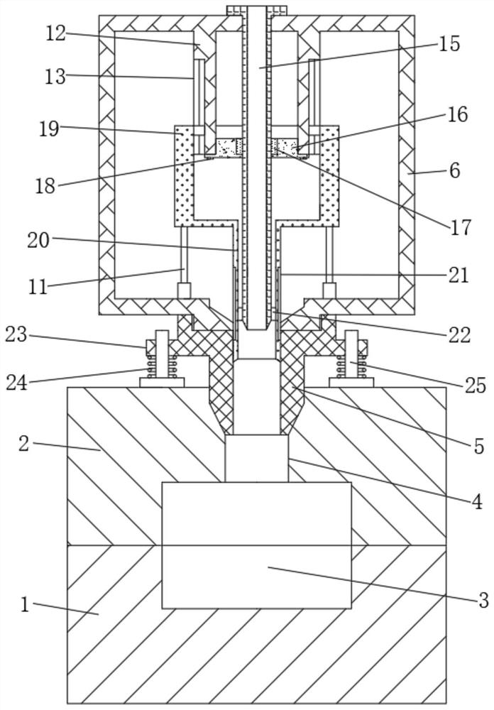
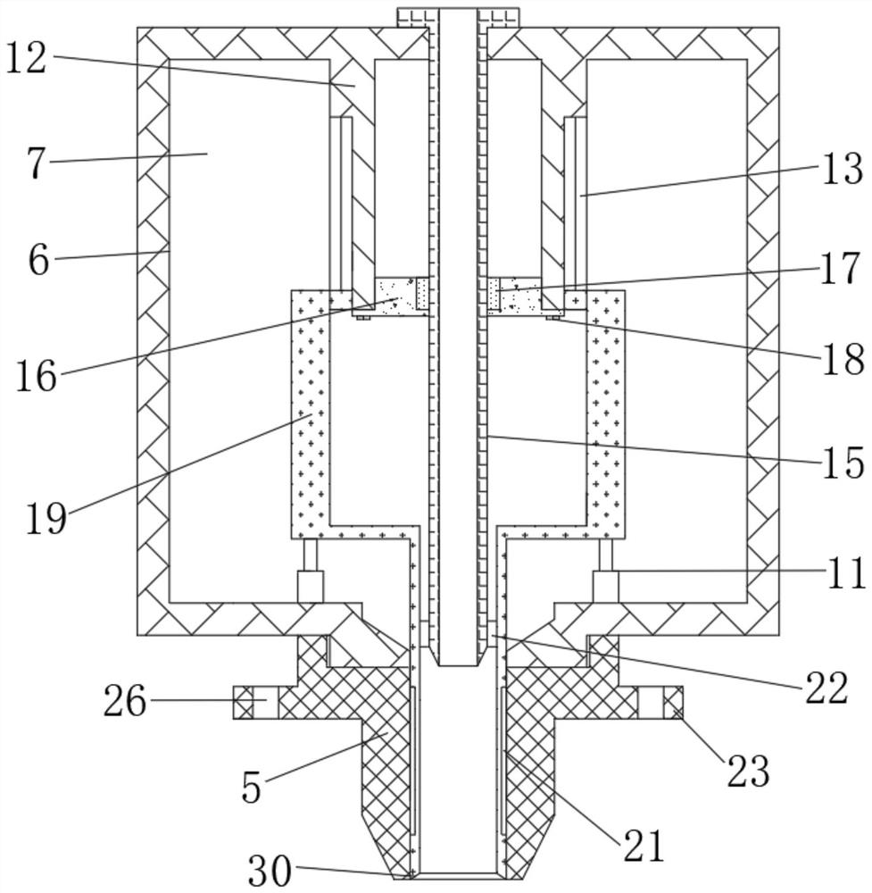
[0028] see Figure 1 to Figure 6 , the present invention provides a technical solution:

[0029] A feeding structure of a high-strength ceramic injection molding device, comprising a lower mold 1, an upper mold 2 is arranged on the upper end of the lower mold 1, and a mold cavity 3 is arranged in the middle inner cavity between the lower mold 1 and the upper mold 2, and the mold cavity The middle of the upper end of 3 is provided with injection gate 4 vertica...


PUM


Abstract

The invention relates to the technical field of injection molding equipment of ceramic molds, in particular to a feeding structure of a high strength ceramic injection molding device. The feeding structure comprises a lower mold, wherein an upper mold is arranged at the upper end of the lower mold, a mold cavity is formed in a middle inner cavity between the upper mold and the lower mold, an injection sprue is vertically formed in the middle of the upper end of the mold cavity downward, and a nozzle is inserted into the inner cavity in the upper end of the injection sprue. The feeding structure has the beneficial effects that by connecting a protecting sleeve slidably in a sleeving manner between the nozzle and an injection pipe, the inner wall of the nozzle is protected by means of the protecting sleeve, and meanwhile, matched with a scraper blade outside the injection pipe, the inner wall of the protecting sleeve is cleaned conveniently and timely, so that the cleaning efficiency ofthe device after injection is improved greatly; by arranging a spring between the nozzle and the upper mold to be matched with a column, a downward impact force of the nozzle is buffered, so that theimpact of injection is acted to the spring and the outer wall of the upper mold to prevent the mold cavity from being affected, and therefore, the injection molding precision is improved favorably.

Description

technical field [0001] The invention relates to the technical field of injection molding equipment for ceramic molds, in particular to a feeding structure of a high-strength ceramic injection molding device. Background technique [0002] After the ceramics are plasticized in the heating barrel of the injection molding machine, the ceramic processing method is injected into the cavity of the closed mold by a plunger or a reciprocating screw to form a product. This method can process products with complex shapes, precise dimensions or inserts, and has high production efficiency. [0003] In the process of ceramic injection molding, the ceramic clay raw material needs to be heated. However, the heated clay has strong adhesion. During injection, the raw material is easy to adhere to the inner wall of the nozzle, which will cause the inner diameter of the nozzle to be reduced or even blocked. The cleaning of the inner wall is more complicated and difficult. At the same time, the...

Claims


Application Information

Patent Timeline
Patent Type & Authority Applications(China)
IPC IPC(8): B28B1/24
CPCB28B1/24
Inventor 徐舒婕
Owner 徐舒婕
Why Eureka
Try Eureka