Special-shaped hole chamfering deburring device

A technology for deburring and special-shaped holes, applied in the direction of grinding drive devices, grinding/polishing safety devices, grinding machines, etc., can solve problems such as low work efficiency, loss, and affecting product processing quality, and reduce resource waste and economic losses , reduce customer complaints and repairs, deburring convenient and quick effect

Inactive Publication Date: 2020-09-18
湖北豪凯汽车零部件有限公司
View PDF0 Cites 1 Cited by
  • Summary
  • Abstract
  • Description
  • Claims
  • Application Information

AI Technical Summary

Problems solved by technology

[0005] In order to solve the above technical problems, the present invention provides a special-shaped hole chamfering and deburring device to solve the problem that when the existing chamfering device chamfers a special-shaped hole, it cannot completely fit the intersecting line for chamfering processing, resulting in some parts chamfering It is relatively large, and the chamfering of some parts is relatively small, and even burrs still remain. Through manual chamfering, the chamfering effect depends on the skill level of the workers, and the work efficiency is relatively low, which seriously affects the processing quality of the product and affects the use. In severe cases, it is necessary to Rework, causing waste of resources and economic losses

Method used


Image

  • Special-shaped hole chamfering deburring device
  • Special-shaped hole chamfering deburring device
  • Special-shaped hole chamfering deburring device

Examples


Embodiment

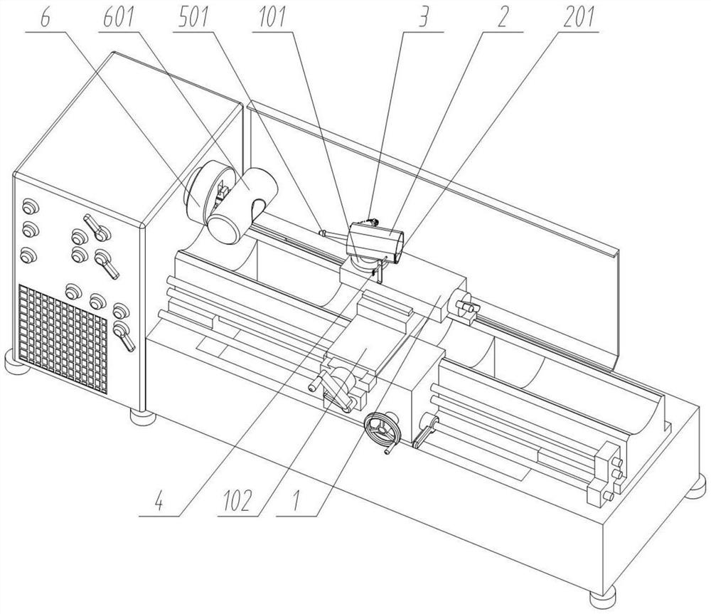
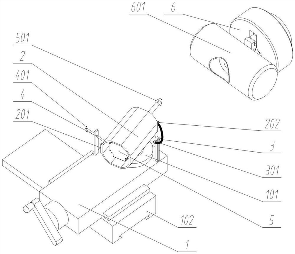
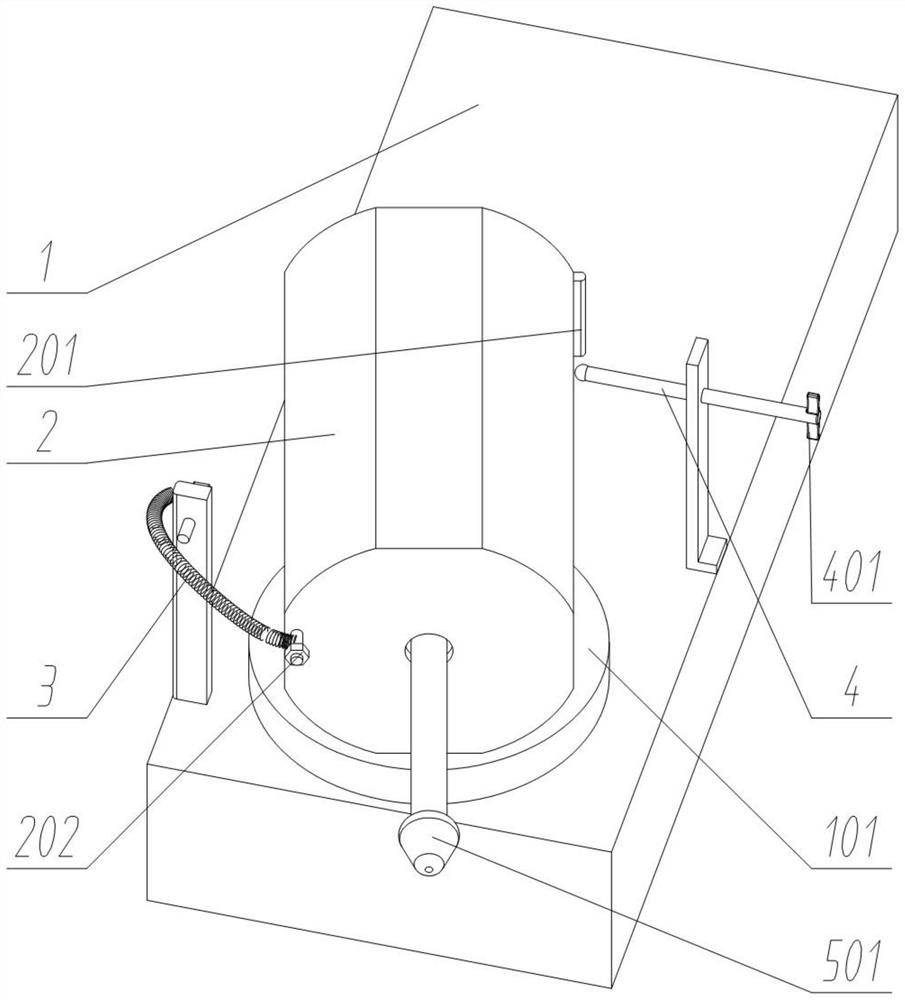
[0027] as attached figure 1 to attach Figure 5 Shown:

[0028] The invention provides a chamfering and deburring device for special-shaped holes, which includes a tailstock 1 and an internal expansion chuck 6; the top of the tailstock 1 is fixedly connected with a group of annular floating tool holders 101 with chute; the top of the tailstock 1 is rotatably connected with a A group of electric grinder mounting bases 2; the front end of the tailstock 1 is rotatably connected to a set of electric grinder limit rods 4; the rear end of the tailstock 1 is fixedly connected to a set of tension springs 3; the tension spring 3 is elastically connected to a set of electric grinder mounting bases 2 A group of floating electric grinders 5 are fixedly connected inside the electric grinder mounting base 2; a group of floating electric grinders 501 are fixedly connected to the drive shaft on the left side of the floating electric grinder 5; A group of rocker shaft parts 601 are tightly c...


PUM


Abstract

The invention provides a special-shaped hole chamfering deburring device, and belongs to the technical field of machining. The device aims to solve the problems that grinding of an existing electric grinder cannot be flexibly adapted to complex parts, the manual grinding flush precision is low, the working efficiency is low, and the unnecessary waste and the loss are caused in a manual operation mode. The device comprises that the top of a tail seat is rotationally connected with a group of electric grinder mounting seats; the front end of the tail seat is fixedly connected with a group of tension springs; the rear end of the tail seat is fixedly connected with a group of electric grinder limit rods; and a group of floating electric grinders is fixedly connected inside the electric grindermounting seats. The floating electric grinders rotate on the tail seat, so that floating electric grinder heads can grind the more complex parts; the tension springs enable the floating electric grinding heads to rotate along with the parts during grinding, so that the cutting effect is more natural; deburring is convenient and rapid, the work which is difficult to complete by manual and common equipment is replaced; and the production quality of the parts is improved, customer complaints are reduced, and the obvious effects on defective products of repairing burr problems are achieved.

Description

technical field [0001] The invention belongs to the technical field of machining, and more specifically relates to a chamfering and deburring device for special-shaped holes. Background technique [0002] When producing products with special-shaped holes and complex edges, the cylindrical raw materials are drilled and cut by a lathe. Due to the processing technology of the lathe, the special-shaped holes and edge trimming will produce burrs and flashes, which will affect the installation during assembly. During processing, manual methods are often used to polish and chamfer the burrs and flashes by using a grinder and sandpaper. [0003] Based on the above, when the existing chamfering device chamfers the special-shaped hole, it cannot completely fit the intersecting line for chamfering processing, resulting in relatively large chamfering in some parts and small chamfering in some parts, and even burrs still remain. Chamfering, the effect of chamfering depends on the skill ...

Claims


Application Information

Patent Timeline
IPC IPC(8): B24B9/00B24B41/04B24B47/12B24B41/06B24B55/00B24B27/00
CPCB24B9/00B24B27/0092B24B41/04B24B41/067B24B47/12B24B55/00
Inventor 王华魏涛夏鑫刘正军李伟
Owner 湖北豪凯汽车零部件有限公司
Why Eureka
Try Eureka