
Waste gas treatment device for environmental protection equipment

A waste gas treatment device and environmental protection equipment technology, applied in transportation and packaging, fixed filter element filter, dispersed particle filtration, etc., can solve problems such as endangering people's health, poor waste gas treatment effect, and polluting the environment

Inactive Publication Date: 2020-09-18
RIZHAO POLYTECHNIC
View PDF0 Cites 4 Cited by
  • Summary
  • Abstract
  • Description
  • Claims
  • Application Information

AI Technical Summary

Problems solved by technology

[0005] The object of the present invention is to provide a waste gas treatment device for environmental protection equipment, to solve the problem that the waste gas treatment effect of the existing waste gas treatment device proposed in the above background technology is poor, and the treated gas will still endanger people's health and cause pollution. environmental problems

Method used


Image

  • Waste gas treatment device for environmental protection equipment
  • Waste gas treatment device for environmental protection equipment
  • Waste gas treatment device for environmental protection equipment

Examples


Embodiment 1

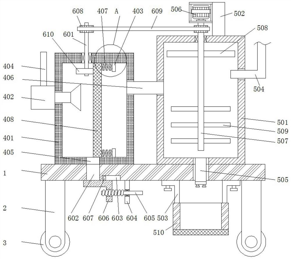
[0028] An exhaust gas treatment device for environmental protection equipment, including a base 1, and a floating object filtering mechanism. Both sides of the bottom of the base 1 are symmetrically fixed with a support plate 2, and the bottom of the support plate 2 is provided with a roller 3; the floating object filter The mechanism is located on the left side of the top of the base 1. The floating substance filtering mechanism includes a filter box 401, an aspirator 402 and a fixed block 403. The filter box 401 is fixed on the top of the base 1, and the aspirator 402 is fixed on the filter box. On the left side of 401 , the aspirator 402 is provided with a suction pipe 404 , and the suction pipe 404 extends to the inside of the filter box 401 .

[0029] Wherein, the bottom of the filter box 401 is provided with a long groove 405 , and the right side of the filter box 401 is fixedly connected with a connecting pipe 406 .

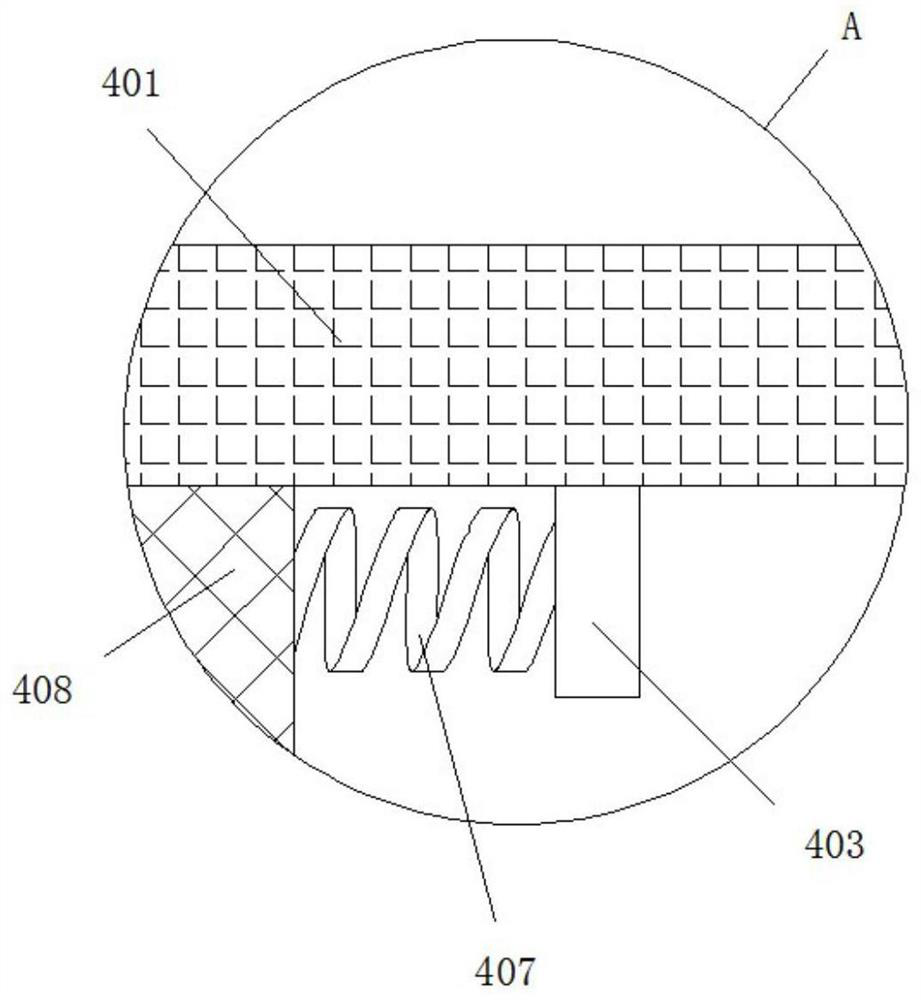
[0030] Wherein, the left sides of the two fixing blo...

Embodiment 2

[0032] The difference from Example 1 is that it also includes the following:

[0033] It also includes a hazardous substance processing mechanism, which includes a processing box 501, a fixing seat 502 and an L-shaped plate 503, the processing box 501 is fixed on the right side of the top of the base 1, and the fixing seat 502 is fixed on the top of the processing box 501 On the top, the L-shaped plate 503 is connected to the bottom of the base 1 by symmetrical bolts, the right end of the connecting pipe 406 is fixedly connected to the left side plate of the processing box 501, and the right side of the processing box 501 is fixedly connected to the liquid inlet. The pipe 504 is fixedly connected to the bottom of the processing box 501 with a discharge pipe 505 .

[0034] Wherein, a motor 506 is fixedly connected to the left side of the fixing base 502, and a long axis 507 is fixedly connected to the output shaft of the motor 506. And mixing rod 509, fan blade 508 is position...

Embodiment 3

[0037] The difference from Example 2 is that it also includes the following:

[0038] Also includes a cleaning mechanism, the cleaning mechanism includes a movable shaft 601, a through groove 602, a limit groove 603 and a square plate 604, the movable shaft 601 is rotatably connected to the top plate of the filter box 401, and the through groove 602 is located under the long groove 405, limiting The bit groove 603 is arranged on the bottom of the base 1, and the square plate 604 is fixedly connected to the bottom of the base 1. The square plate 604 is threaded with a threaded rod 605, and the left end of the threaded rod 605 is threaded with a clamping plate 606. The top of the clamping plate 606 It is slidably connected with the bottom of the base 1 , and the top of the clamping plate 606 is fixedly connected with a limiting block 607 , and the limiting block 607 is slidably connected inside the limiting groove 603 .

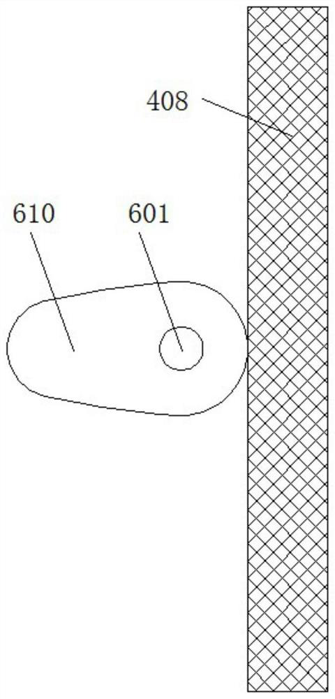
[0039] Wherein, the top of the movable shaft 601 and the ...


PUM


Abstract

The invention relates to the technical field of environment-friendly waste gas treatment, and particularly discloses a waste gas treatment device for environment-friendly equipment; the waste gas treatment device comprises a base, and further comprises a floating object filtering mechanism; supporting plates are symmetrically and fixedly connected to the two sides of the bottom of the base, and idler wheels are arranged at the bottoms of the supporting plates; the floating object filtering mechanism is arranged on the left side of the top of the base, the floating object filtering mechanism comprises a filtering box, an air suction machine and a fixing block, the filtering box is fixedly connected to the top of the base, the air suction machine is fixedly connected to the left side of thefiltering box, an air suction pipe is arranged on the air suction machine, and the air suction pipe extends into the filtering box. Floating objects in waste gas can be filtered through a filter plate, and primary filtration of the waste gas is realized; the waste gas is introduced into a treatment box to be mixed with a treatment solution, so that harmful substances are treated, finally, treatedimpurities are filtered through a filter screen of a fixed box, and meanwhile, the filter plate is driven to vibrate through rotation of a cam, so that the floating objects on the filter plate are convenient to clean.

Description

technical field [0001] The invention relates to the technical field of environmental protection waste gas treatment, in particular to a waste gas treatment device for environmental protection equipment. Background technique [0002] Commonly used methods for treating waste gas in waste gas treatment devices include adsorption method, absorption method, catalytic combustion method, thermal combustion method, etc. When choosing a purification method, the county should choose a method with low cost, low energy consumption, and no secondary pollution according to the specific situation, try to turn harm into benefit, and fully recycle components and waste heat. In most cases, the petrochemical industry adopts methods such as condensation, absorption, and direct combustion due to the high concentration of exhaust gas; the coating construction, printing and other industries adopt methods such as adsorption and catalytic combustion due to the low concentration of exhaust gas. [0...

Claims


Application Information

Patent Timeline
IPC IPC(8): B01D53/78B01D46/10B01D46/00B01D29/03
CPCB01D53/78B01D46/10B01D29/03B01D46/76
Inventor 郑伟石艳玲
Owner RIZHAO POLYTECHNIC
Learn More