Non-contact encoder

A non-contact, encoder technology, applied in the field of encoders, can solve problems such as stability to be improved, garbled signals of slot-type photoelectric switches, increased production and assembly costs, etc., and achieves novel design, simplified structure, and reduced production and assembly. cost effect

Pending Publication Date: 2020-09-15
DONGGUAN LINJVE IND INVESTMENTS
View PDF1 Cites 1 Cited by
  • Summary
  • Abstract
  • Description
  • Claims
  • Application Information

AI Technical Summary

Problems solved by technology

This patent utilizes the groove-type photoelectric switch to realize the functions of potentiometer and encoder, but the groove-type photoelectric switch is a direct photoelectric switch, which needs to be equipped with a code disc with a complex structure, which increases the production and assembly costs. At the same time, the groove-type photoelectric switch and the code disc The space between them is very easy to transmit light, which makes the groove photoelectric switch easy to generate garbled signals, and the stability needs to be improved

Method used


Image

  • Non-contact encoder
  • Non-contact encoder
  • Non-contact encoder

Examples


Embodiment Construction

[0021] Specific embodiments of the present invention are described with reference to the accompanying drawings.

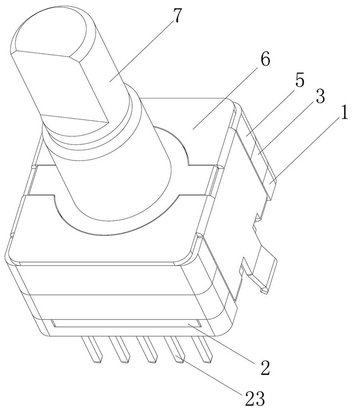
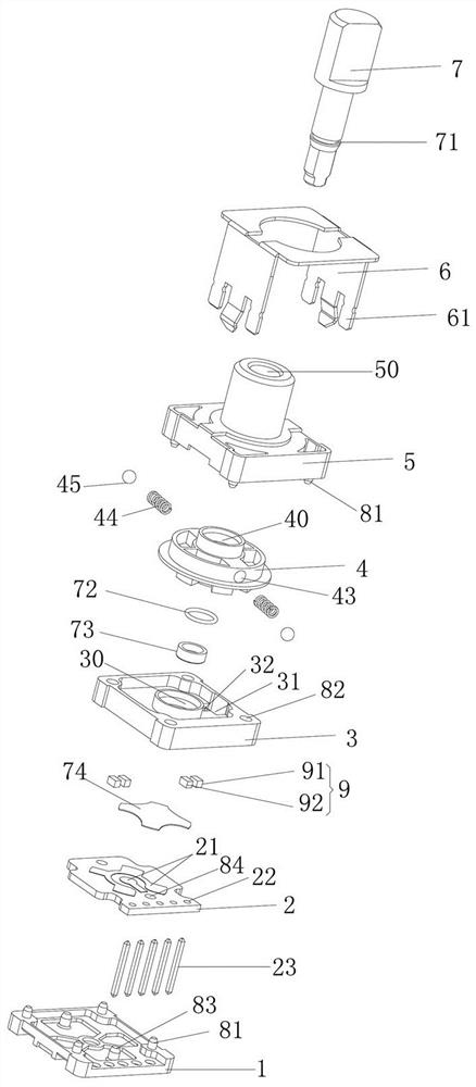
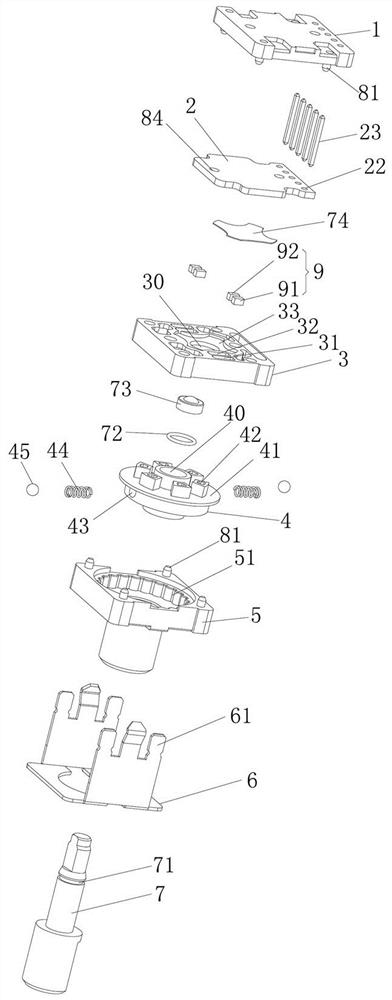
[0022] Such as Figure 1-5 As shown, the non-contact encoder includes a shaft core 7, a bracket 6, a shaft sleeve 5, a fluctuation plate 4, two sets of optical components 9, a middle shell 3, a pusher 73, a collar 72, a PCB board 2, and a bottom plate 1, The undulating disk 4 is arranged between the shaft sleeve 5 and the middle shell 3, and a positioning structure for producing a gear feel is arranged between the undulating disk 4 and the shaft sleeve 5. The optical assembly 9 includes a light source 91 and a receiving source both located on the same side of the undulating disk 4. 92. The undulating disk 4 has a reflective surface 41. The light emitting source 91 emits light in the direction of the reflective surface 41 and reflects the light to the receiving source 92 through the reflective surface 41. The undulating disk 4 is also provided with six light shields...


PUM


Abstract

The invention relates to a non-contact encoder. The encoder comprises a shaft core, a support, a shaft sleeve, a fluctuation disc, optical assemblies, a middle shell, a PCB and a bottom plate. The fluctuation disc is arranged between the shaft sleeve and the middle shell, a positioning structure for generating gear hand feeling is arranged between the fluctuation disc and the shaft sleeve, each optical assembly comprises a light emitting source and a receiving source which are positioned on the same side of the fluctuation disc, the fluctuation disc is provided with a reflecting surface, the light emitting source emits light towards the reflecting surface and reflects the light to the receiving source through the reflecting surface, and the fluctuation disc is provided with a shading partcapable of preventing the light from entering the receiving source. The optical assemblies are arranged on the same side of the light reflecting surface of the fluctuation disc, so that light emittedby the light emitting sources is reflected into the receiving sources through the light reflecting surface of the fluctuation disc to form a lower loop, and when the fluctuation disc rotates, shadingcolumns can shade light receiving holes to enable the receiving sources not to receive light to form an open circuit, and the encoding function is completed; gear positioning hand feeling is providedthrough matching of steel balls and shaft sleeve positioning teeth, and the rotating service life of a product is prolonged through a spring and steel ball positioning structure.

Description

technical field [0001] The invention relates to the technical field of encoders, in particular to a non-contact photoelectric encoder. Background technique [0002] With the continuous development of society, electronic products are updated and iterated rapidly. In the current electronic products, various switches need to be used. Among them, the rotary switch is widely used by people because of the convenient operation of shifting. In some rotary switches It is necessary to use a body hollow shaft encoder. For example, the Chinese invention patent with application number CN201910591080.5 discloses a knob, including a knob body, a code disc, a circuit board, and a groove-type photoelectric switch. The circuit board is provided with a first-type interface and the second type of interface, the first type of interface and the second type of interface are used to connect the slot photoelectric switch. By selecting the number of slot-type photoelectric switches and the number of...

Claims


Application Information

Patent Timeline
Patent Type & Authority Applications(China)
IPC IPC(8): G01D5/347
CPCG01D5/3473
Inventor 舒斯龙何德帆
Owner DONGGUAN LINJVE IND INVESTMENTS
Why Eureka
Try Eureka