Timepiece including electric power generator

A technology of generators and clocks, which is applied in the field of clocks and watches, and can solve the problems of reduced automaticity of clocks and watches

Inactive Publication Date: 2003-07-30
ASULAB SA
View PDF0 Cites 0 Cited by
  • Summary
  • Abstract
  • Description
  • Claims
  • Application Information

AI Technical Summary

Problems solved by technology

But the automaticity of said timepiece decreases with time, which is clearly not desired

Method used


Image

  • Timepiece including electric power generator
  • Timepiece including electric power generator
  • Timepiece including electric power generator

Examples


Embodiment Construction

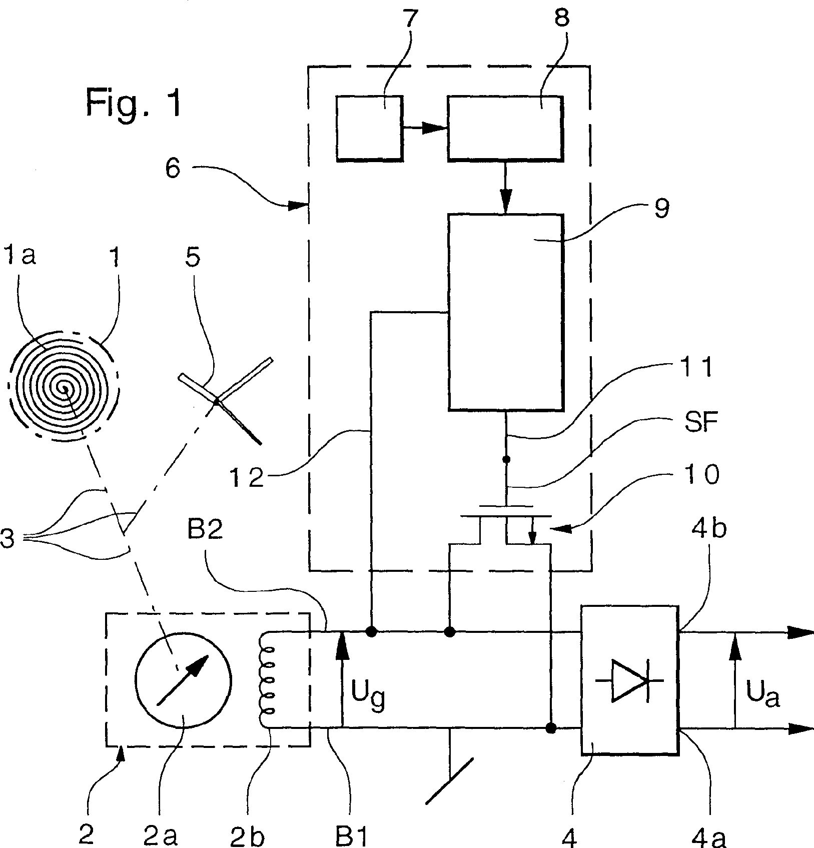
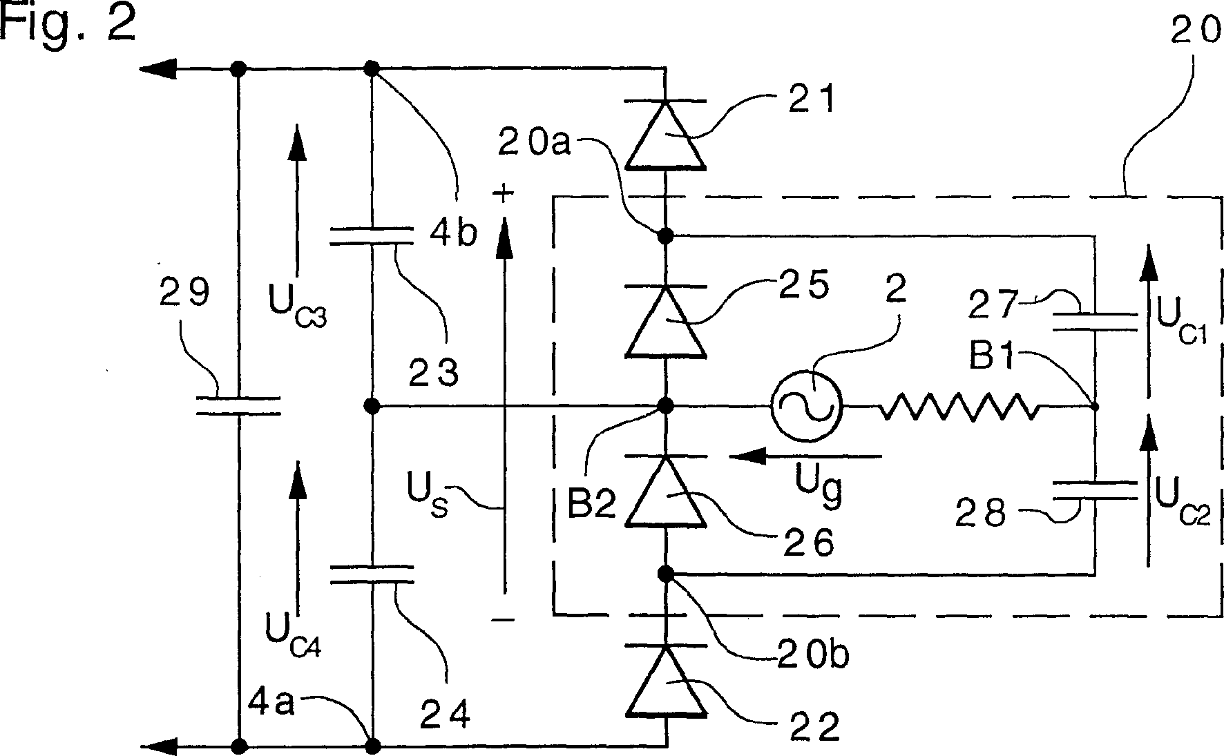
[0028] Reference is first made to FIG. 1, which is an overall simplified schematic diagram of a timepiece according to the present invention. It is worth noting that a part of this schematic diagram relates to the regulating circuit, which is used to control or limit the rotational speed of the generator of this timepiece, which will not be described in detail here, and those skilled in the art refer to this patent application. The description of Swiss Patent Application No 686 332 filed in person's name enables the design of such a restraint device to be easy. However, in order to be able to understand the present invention more easily, a brief review of the necessary components in the schematic and the operation of this regulation circuit will be made here.

[0029] Said timepiece according to the invention comprises a mechanical energy source consisting of a barrel 1 containing a mainspring 1a of the conventional timepiece type, which is wound manually or automatically.

...


PUM

PropertyMeasurementUnit
Capacitanceaaaaaaaaaa

Abstract

Timepiece including: a spring housed in said barrel, an electric power generator coupled to said barrel, a rectifier circuit connected to said generator, and a regulator circuit supplied by the direct voltage from the rectifier circuit and intended to control the rotational speed of the generator. The rectifier circuit comprises: a voltage doubler rectifier connected to the output of the generator, a first capacitor and a first diode connected in series between said first output terminal of the rectifier and the first output terminal of the generator, a second capacitor and a second diode connected in series between the first output terminal of the generator and the second output terminal of the rectifier.

Description

technical field [0001] The present invention relates to an electronic timepiece, in particular a timepiece in which electrical energy is generated by a generator driven by a mainspring in a barrel. Background technique [0002] A timepiece with these features in the example disclosed in Swiss Patent Application No 686 332 has the same accuracy as a conventional timepiece, depending on the reference pulses generated by a signal supplied by a quartz oscillator, the frequency of which is determined by the reference pulses The rotation speed of the generator rotor and the rotation speed of the hand showing the current time are displayed. [0003] Furthermore, this timepiece contains neither a battery nor an energy storage device, since the power supply of its electronic circuits is ensured by the electrical energy supplied by its generator, the rotor of which is connected to the mechanical energy source of the timepiece, which The source of mechanical energy consists of a mains...

Claims


Application Information

Patent Timeline
IPC IPC(8): G04B1/10G04B17/00G04C3/00G04C10/00
CPCG04C10/00
Inventor P·-A·法里纳E·贝尔纳斯科尼
Owner ASULAB SA
Why Eureka
Try Eureka