


Quick Research
Generate reliable direction feasibility study reports for your R&D in just a few steps.

Technical Q&A
Discover and master advanced knowledge NOW. Basics, ideas, possibilities, all at once.

Find Solutions
As an expert in R&D theories, this can generate solutions to your technical problems instantly.

Evaluate Feasibility
Analyze your overall solution with one click, know your potential R&D risks in advance.

Monitor Landscape
Get weekly tech updates, stay abreast of the latest tech innovations and key insights.
Unmanned aerial vehicle emergency rescue underwater robot for circuit inspection and measurement
A UAV and circuit technology, applied in the field of UAV, can solve the problems of poor inspection effect, poor buffering effect, UAV body falling damage, etc., to achieve the effect of being easy to carry, easy to use, and improve handling stability
- Summary
- Abstract
- Description
- Claims
- Application Information
AI Technical Summary
Problems solved by technology
Method used
Image


Examples
Embodiment 1
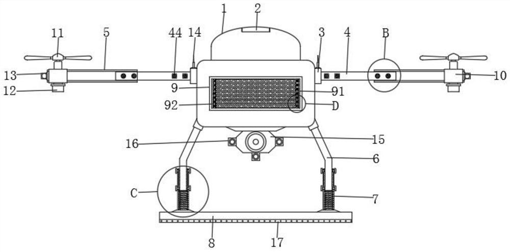
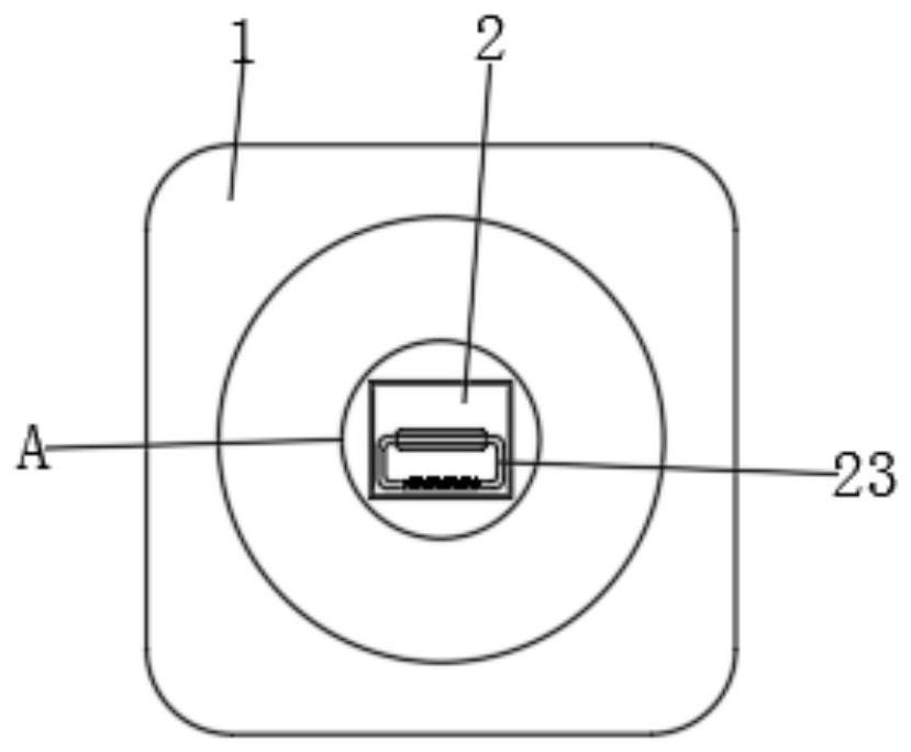
[0043] see figure 1 , figure 2 and image 3 , the groove 2 includes a fixed plate 21, the inside of the fixed plate 21 is provided with a first movable groove 22, the inside of the first movable groove 22 is provided with a handle 23, the outer wall of the handle 23 is provided with a protective cover 24, and the shape of the handle 23 It is in the shape of mouth.
[0044] In this embodiment, when using the drone body 1, the user moves the drone body 1 to the work place by holding the handle 23, which solves the problem that the traditional drone body 1 is not provided with a handle 23 and the surface is smooth. The shape makes it inconvenient for the user to take and cause the problem that it is easy to drop to the ground during transportation, which improves the stability of transportation and prevents damage to the drone body 1. At the same time, when the handle 23 is not needed, the handle 23 can be used 23 is rotated in the first movable groove 22 in the fixed plate 2...
Embodiment 2
[0046] see figure 1 , Figure 4 and Figure 5 , the fixed support rod 4 comprises a hollow groove 41, the inner wall of the hollow groove 41 is provided with an elastic post 42, the outer wall of the elastic post 42 is covered with a first spring 43, and one end of the elastic post 42 is provided with a fixed block 44, the movable support rod A second movable slot 51 is opened inside the 5 , and a fixed slot 52 matching the fixed block 44 is opened on the outer wall of the movable support rod 5 .
[0047] In this embodiment, when the UAV body 1 is performing inspection work, the second movable groove 51 inside the movable support rod 5 slides on the outer wall of the fixed support rod 4, and then the fixed block 44 is snapped into the fixed groove 52 , the length of its support bar can be extended. In addition, if the drone body 1 is not used, the length of its support bar can also be shortened, which avoids the problem that the drone body 1 takes up a lot of space due to th...
Embodiment 3
[0049] see figure 1 and Figure 6 , the support rod 6 includes a block 61, the outside of the block 61 and the inner wall of the support column 7 are provided with a card slot 71, the bottom end of the support rod 6 is provided with a buffer block 72, and the bottom end of the buffer block 72 is located at the support A second spring 73 is provided inside the column 7 , and a fastening block 74 is provided on the outer wall of the support column 7 .
[0050] In this embodiment, the support rod 6 can be firmly installed in the support column 7, which avoids the weak support force at the bottom of the drone body 1 during the landing process, which causes the drone body 1 to be easily damaged. Problem, at the same time, in the process of landing, the buffer block 72 and the second spring 73 can effectively buffer the landing, which solves the problem that the existing UAV body 1 has poor buffering effect and easily causes damage to the UAV body 1 due to falling. problems and pr...
PUM
 Abstract
Description
Claims
Application Information
 - R&D Engineer
- R&D Manager
- IP Professional
- Industry Leading Data Capabilities
- Powerful AI technology
- Patent DNA Extraction
Browse by: Latest US Patents, China's latest patents, Technical Efficacy Thesaurus, Application Domain, Technology Topic, Popular Technical Reports.
© 2024 PatSnap. All rights reserved.Legal|Privacy policy|Modern Slavery Act Transparency Statement|Sitemap|About US| Contact US: help@patsnap.com