Cooling ring and cutting tool

A cutting tool and cooling ring technology, applied in the field of metal cutting processing, can solve the problems of difficult manufacturing, difficult to widely use, low cost performance, etc., and achieve the effect of reducing processing cost, wide application range and low processing difficulty

Active Publication Date: 2020-09-11
ZHUZHOU CEMENTED CARBIDE CUTTING TOOLS CO LTD
View PDF11 Cites 0 Cited by
  • Summary
  • Abstract
  • Description
  • Claims
  • Application Information

AI Technical Summary

Problems solved by technology

[0003] However, the internal cooling tools in the prior art usually need to set complex cooling channels inside, and even need to set multiple intersecting cooling channels inside. The cooling channels inside the tool are difficult to manufacture and the cost is high, especially when hard materials are used. The high-strength tool is manufactured, and the cooling channel needs to be removed by electric sparks, which is very low in processing efficiency and increases the processing cost, resulting in a decrease in the cost performance of the cutting tool
Due to the low cost performance, in the actual cutting process, the application range of cutting tools with internal cooling structure is limited, and it is difficult to be widely used

Method used


Image

  • Cooling ring and cutting tool
  • Cooling ring and cutting tool
  • Cooling ring and cutting tool

Examples


Embodiment Construction

[0034] The present invention will be further described in detail below in conjunction with the accompanying drawings and specific embodiments.

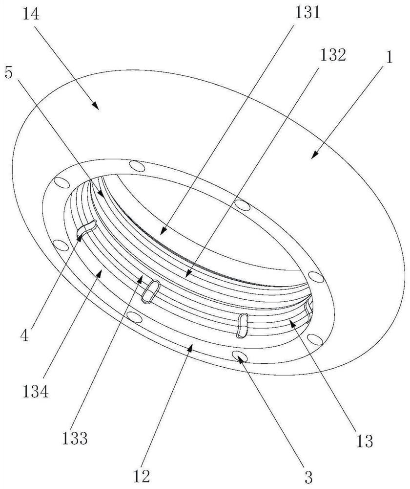
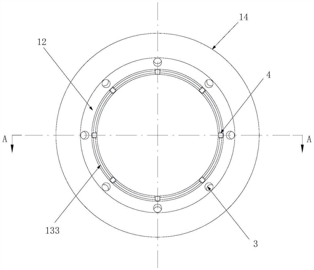
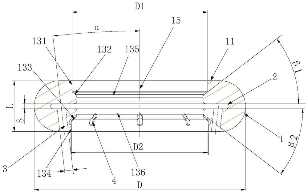
[0035] Figure 1 to Figure 3 An embodiment of the cooling ring of the present invention is shown, the cooling ring includes an annular body 1, the annular body 1 includes an upper surface 11, a lower surface 12, an inner peripheral surface 13 and an outer periphery connecting the upper surface 11, the lower surface 12 Surface 14, the inner peripheral surface 13 is provided with an annular inner groove 2 along the circumferential direction of the annular body 1, and more than one cooling hole 3 is provided on the lower surface 12, the cooling hole 3 communicates with the inner groove 2, and the cooling hole 3 The direction of extension is from top to bottom to the axial centerline 15 of the annular body 1, and the cooling liquid can be stored in the inner groove 2, and sprayed to the axial centerline of the annular body 1 through the c...


PUM


Abstract

The invention discloses a cooling ring and a cutting tool. The cooling ring includes a ring-shaped body, the ring-shaped body includes an upper surface, a lower surface and an internal and an externalcircumferential surface connecting the upper surface and the lower surface, a ring-shaped inner groove is formed in the internal circumferential surface along the circumferential direction of the ring type body, more than one cooling hole is formed in the lower surface, the cooling holes communicate with the inner groove, and the extension direction of the cooling holes is to gather toward an axial center line of the ring-shaped body from top to bottom. The cooling ring is simple in structure, convenient to machine and wide in application range. A liquid storing chamber capable of storing cooling liquid is arranged on the circumferential surface of a tool between a cutting part and a clamping part of the cutting tool, a drainage groove is formed in the circumferential surface of the toolof the clamping part, the liquid storing chamber communicates with the drainage groove, the cutting tool further includes the cooling ring, the cooling ring is arranged on the external part of the liquid storing chamber, and the internal circumferential surface of the cooling ring are matched with the liquid storing chamber to form a sealing cavity communicating with the inner groove. The coolingliquid penetrates through the drainage groove, liquid storing chamber, the inner groove and the cooling holes successively to spray to a cutting edge, and the cutting tool is good in cooing effect, low in cost, and convenient to mount and position.

Description

technical field [0001] The invention relates to the field of metal cutting, in particular to a cooling ring and a cutting tool thereof. Background technique [0002] The internal cooling tool with its own cooling structure has low cutting temperature and high chip removal efficiency. It not only has long cutting life, but also has good surface quality and high dimensional accuracy. It has a wide application prospect in theory. [0003] However, the internal cooling tools in the prior art usually need to set complex cooling channels inside, and even need to set multiple intersecting cooling channels inside. The cooling channels inside the tool are difficult to manufacture and the cost is high, especially when hard materials are used. The manufactured high-strength cutting tools need to use electric sparks for material removal when machining cooling channels, which results in very low processing efficiency, which increases processing costs and leads to a decline in the cost pe...

Claims


Application Information

Patent Timeline
Patent Type & Authority Applications(China)
IPC IPC(8): B23C5/28B23C5/00
CPCB23C5/00B23C5/28
Inventor 江爱胜周红翠王社权刘伟
Owner ZHUZHOU CEMENTED CARBIDE CUTTING TOOLS CO LTD
Why Eureka
Try Eureka