Continuous sintering furnace for ceramic fiber material

A technology of ceramic fiber and sintering furnace, which is applied in the production of ceramic materials, furnace, charge and other directions, can solve the problems of easy entanglement and breakage of fiber filaments, difficulty in ensuring product consistency, and brittle fiber filaments, etc., to achieve uniformity and sintering. Good consistency, ensure consistency and uniformity, solve the effect of winding and breaking

Active Publication Date: 2020-09-08
48TH RES INST OF CHINA ELECTRONICS TECH GROUP CORP +1
View PDF4 Cites 2 Cited by
  • Summary
  • Abstract
  • Description
  • Claims
  • Application Information

AI Technical Summary

Problems solved by technology

Due to the characteristics of ceramic fiber materials, the fiber filaments are brittle and easily entangled. The commonly used tunnel furnace is used for sintering. The fiber material needs a carrier. It is difficult to guarantee the stability and consistency of the product during the sintering process of the fiber material.
Therefore, the quality of ceramic fiber materials is average at present, and it is difficult to produce high-quality high-alumina ceramic fiber materials with good performance.
The existing ceramic fiber material preparation equipment usually adopts the method of tunnel furnace propulsion, but in the production process, the fiber material is supported by the existing carrier, the fiber filaments are easily entangled and broken during the sintering process, and the layers of the sintered fiber material are heated unevenly, making it difficult to reach different positions The consistency of the mechanical properties of the wire will greatly affect the performance and comprehensive performance of the ceramic fiber material
Disadvantages of the existing technology: most of the existing ceramic fiber material products are continuously produced by tunnel furnaces. During the sintering process, the fiber threads are wound on the object in multiple layers and then sintered. It is difficult to ensure the consistency of the products in this way.

Method used


Image

  • Continuous sintering furnace for ceramic fiber material
  • Continuous sintering furnace for ceramic fiber material
  • Continuous sintering furnace for ceramic fiber material

Examples


Embodiment Construction

[0024] The present invention will be described in further detail below in conjunction with the accompanying drawings and specific embodiments.

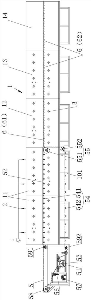
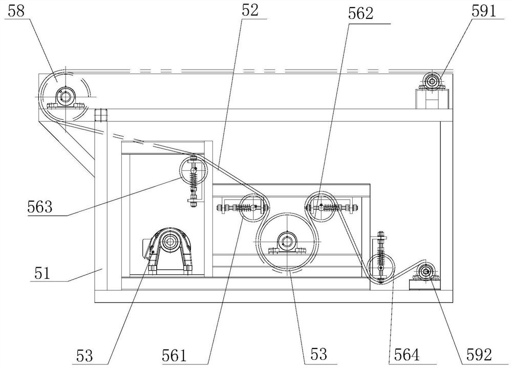
[0025] like figure 1 and figure 2 As shown, the continuous sintering furnace for ceramic fiber materials in this embodiment includes a furnace body assembly 1, a conveying system and an exhaust pipe 2. The furnace body assembly 1 is divided into a heating zone, a furnace body 11, and a rapid heating zone along the conveying direction. Furnace body 12, constant temperature zone furnace body 13 and cooling zone furnace body 14. The conveying system includes a mesh belt conveying part 5 and a roller conveying part 6. The mesh belt conveying part 5 is used for conveying the furnace body 11 in the heating zone, and the roller conveying part 6 is used for the furnace body 12 in the rapidly rising temperature zone, the furnace body 13 in the constant temperature zone and the furnace body 13 in the constant temperature zone. The transfer o...


PUM


Abstract

The invention discloses a continuous sintering furnace for a ceramic fiber material. The continuous sintering furnace comprises a furnace body assembly, a transfer system and an exhaust duct; the furnace body assembly is divided into a heating zone furnace body, a rapid heating zone furnace body, a constant temperature zone furnace body and a cooling zone furnace body in sequence along the transfer direction; a heating element and a temperature measuring element are respectively arranged in the heating zone furnace body, the rapid heating zone furnace body and the constant temperature zone furnace body; the exhaust duct is arranged at the top of the heating zone furnace body; the transfer system comprises a mesh belt transfer part and a roller transfer part; and the mesh belt transfer partis used for transferring the heating area furnace body, and the roller transfer part is used for transferring the rapid heating zone furnace body, the constant temperature zone furnace body and the cooling zone furnace body. The continuous sintering furnace for the ceramic fiber material provided by the invention has the advantages of being capable of effectively solving the problem of winding and breaking of fiber filaments, and effectively guaranteeing the consistency and uniformity of products.

Description

technical field [0001] The invention relates to sintering equipment for ceramic fiber materials, in particular to a continuous sintering furnace for ceramic fiber materials. Background technique [0002] With its excellent physical and chemical properties, ceramic fiber materials are widely used in aerospace, national defense, automobiles and high temperature heat insulation and other fields. Due to the characteristics of ceramic fiber materials, the fiber filaments are brittle and easy to entangle. The commonly used tunnel furnace is used for sintering. The fiber material needs a carrier. It is difficult to guarantee the stability and consistency of the product during the sintering process of the fiber material. Therefore, the quality of the current ceramic fiber materials is average, and it is difficult to produce high-quality high-alumina ceramic fiber materials with good performance. The existing ceramic fiber material preparation equipment usually adopts the method of ...

Claims


Application Information

Patent Timeline
Patent Type & Authority Applications(China)
IPC IPC(8): F27B9/24F27B9/30F27B9/34F27B9/36
CPCF27B9/243F27B9/2407F27B9/30F27B9/34F27B9/36F27B2009/2446F27M2001/1504F27M2003/04Y02P40/60
Inventor 张滔黄绍明许鹏
Owner 48TH RES INST OF CHINA ELECTRONICS TECH GROUP CORP
Why Eureka
Try Eureka