A cooling device for numerical control fan

A cooling device and fan technology, applied in cooling/ventilation devices, parts of pumping devices for elastic fluids, electromechanical devices, etc., can solve high cost, reduce technical cooling effects, reduce air cooling effect on cooling media, etc. problem, to achieve the effect of improving stability, ensuring stability, and good protection effect

Active Publication Date: 2022-01-28
安徽庐风风机有限公司
View PDF5 Cites 2 Cited by
  • Summary
  • Abstract
  • Description
  • Claims
  • Application Information

AI Technical Summary

Problems solved by technology

For example, "a cooling device for numerically controlled fan" (Patent No.: CN 209053835 U) disclosed in China Patent Network, the technical problem solved by this patent is that the existing heat dissipation method usually adopts the bearing box, and the bearing box is installed with the The water inlet and the water outlet are connected internally, and the cooling water circulates inside the bearing box to take away the heat and complete the cooling of the main shaft and the bearing. However, this method requires the introduction of a separate water pump from the outside, and the cost is high. The patent adopts the design of the ring This technical problem has been solved under the interaction between the separator, the air channel, the cooling channel, the liquid outlet and the liquid injection port, but there are still some deficiencies in this patent, which ignores the source of heat generation. In this state, the amount of heat transferred from the main shaft to the transmission bearing will increase sharply, which reduces the cooling effect of this technology, and cannot purify and filter the air entering the air passage, and a large amount of impurities accumulate in the air passage, which is easy to reduce the air The cooling effect on the cooling medium, therefore, at this stage there is an urgent need for a cooling device for numerically controlled fans to solve the above problems

Method used


Image

  • A cooling device for numerical control fan
  • A cooling device for numerical control fan
  • A cooling device for numerical control fan

Examples


Embodiment Construction

[0037] The following will clearly and completely describe the technical solutions in the embodiments of the present invention with reference to the accompanying drawings in the embodiments of the present invention. Obviously, the described embodiments are only some, not all, embodiments of the present invention. Based on the embodiments of the present invention, all other embodiments obtained by persons of ordinary skill in the art without creative efforts fall within the protection scope of the present invention.

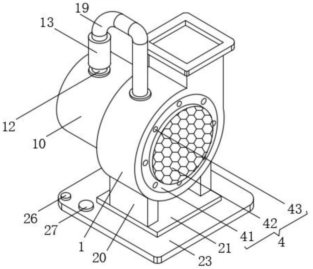
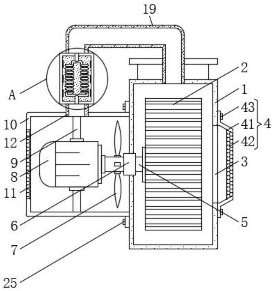
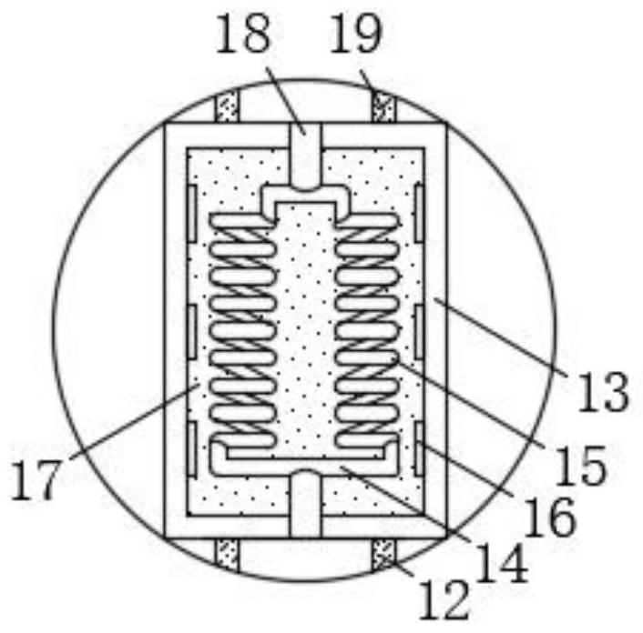
[0038] see Figure 1-5, the present invention provides a technical solution: a cooling device for a numerically controlled fan, including a casing 1, an impeller 2 is arranged inside the casing 1, and an air inlet 3 is provided on the surface of the casing 1 corresponding to the position of the impeller 2, And the surface of the casing 1 is detachably connected to the position corresponding to the air inlet 3 with a purification device 4, and the side of the impell...


PUM


Abstract

The invention discloses a cooling device for a numerically controlled fan, which belongs to the technical field of fan cooling, and comprises a casing, an impeller is arranged inside the casing, and an air inlet is provided on the surface of the casing corresponding to the position of the impeller, and the casing The position corresponding to the air inlet on the surface is detachably connected with a purification device. In the present invention, through the effective cooperation between the designed purification device, spiral tube, cooling sheet, cooling liquid and noise reduction shield, impurities can be prevented from adhering to the bearing box, and impurities can not only be prevented from increasing in the main shaft and the bearing box. The friction force between the bearings can also ensure the cooling effect of the air flowing in the air channel on the cooling water or lubricating oil flowing in the cooling channel, and the heat dissipation and cooling of the motor can reduce the heat generated by the motor during operation to a certain extent. The main shaft is transmitted to the bearings in the bearing box, so that the bearings in the bearing box can be further protected, and the stability of the bearings in the bearing box is guaranteed.

Description

technical field [0001] The invention belongs to the technical field of fan cooling, and in particular relates to a cooling device for a numerically controlled fan. Background technique [0002] The fan is a machine that relies on the input mechanical energy to increase the gas pressure and discharge the gas. It is a driven fluid machine. Fan is the customary abbreviation for gas compression and gas conveying machinery in China. Generally speaking, fans include ventilators, blowers, and wind generators. [0003] The main structural components of the fan are the impeller, casing, air inlet, bracket, motor, pulley, coupling, muffler, transmission parts (bearings), etc. [0004] The CNC fan is a modern intelligent fan. In order to ensure that the CNC fan can work for a long time, it is necessary to use a corresponding cooling device to cool the CNC fan. For example, "a cooling device for numerically controlled fan" (Patent No.: CN 209053835 U) disclosed in China Patent Network...

Claims


Application Information

Patent Timeline
Patent Type & Authority Patents(China)
IPC IPC(8): F04D29/056F04D29/58F04D29/70F25B21/02H02K5/10H02K5/24H02K9/19
CPCF04D29/5806F04D29/582F04D29/703F04D29/056H02K9/19H02K5/24H02K5/10F25B21/02
Inventor 傅强杨从贵管照正彭拥军王晓松周玉红徐经存
Owner 安徽庐风风机有限公司
Why Eureka
Try Eureka