
An easy-to-install CNC fan

A fan and mounting pin technology, which is applied to the components of the pumping device for elastic fluid, pump device, mechanical equipment, etc. Ease of installation

Active Publication Date: 2021-09-24
安徽庐风风机有限公司
View PDF11 Cites 1 Cited by
  • Summary
  • Abstract
  • Description
  • Claims
  • Application Information

AI Technical Summary

Problems solved by technology

[0004] The purpose of the present invention is to provide an easy-to-install numerically controlled fan to solve the above-mentioned background technology. According to the Chinese patent (CN209324698U), an easy-to-install fan patent is described in this article. The combination of fixing frame, shell, connecting block, connecting rod, fixing block, clamping rod, spring and clamping slot can effectively solve the complicated problem of traditional fan installation process. This device can effectively and conveniently install the fan, In order to achieve the purpose of reducing the user's labor force, improve work efficiency, and at the same time ensure the stability of the use of the fan, by setting the card slot, the card rod can be limited, thereby achieving the effect of card connection, by setting the limit slot And the limit block can limit the shell and improve the stability. By setting the vent and the air outlet pipe, the normal operation of the fan body can be realized. By setting the handle, it is easy to operate the connecting rod. By setting the through hole, It can achieve the purpose of connecting the clamp rod through the fixed frame and the clamp slot, but the device is not set up as an assembled type, and the driving mechanism of the fan is fixedly installed on the fan, which is extremely inconvenient when the fan is overhauled or inspected. Convenience question

Method used


Image

  • An easy-to-install CNC fan
  • An easy-to-install CNC fan
  • An easy-to-install CNC fan

Examples


Embodiment Construction

[0021] The technical solution of this patent will be further described in detail below in conjunction with specific embodiments.

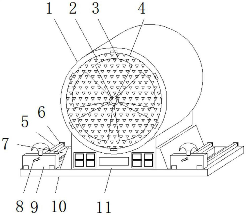
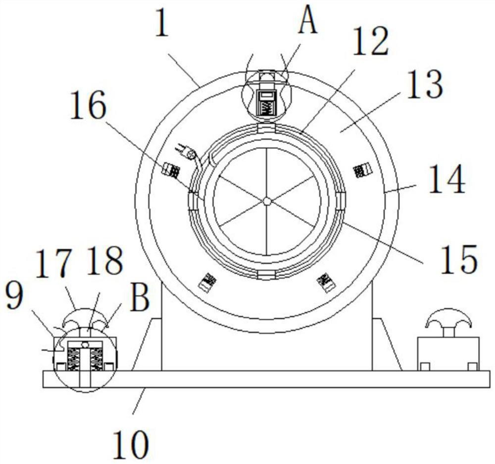
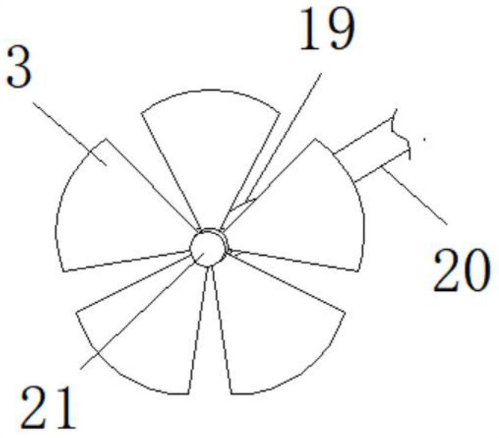
[0022] see Figure 1-5 , a numerically controlled fan that is easy to install, including a casing 1, fan blades 3, a moving block 9, a casing 11, a rear cover 13, a drive motor 16, a mounting pin 18 and a snap-in shaft 22, the front of the casing 1 The front groove 4 and the rear groove 14 are respectively opened on the back side. The bottom of the casing 1 is fixedly installed with an organic casing 11, and the bottom of the casing 11 is fixedly installed with a bottom plate 10. Both sides of the casing 11 are located The interior is provided with a stroke groove 7, the inner side of the rear groove 14 is detachably installed with a rear cover 13, the side of the rear cover 13 is provided with a wire groove 15, and the side of the rear cover 13 is fixedly installed with a drive Motor 16, described casing 11 both sides are positioned at the top of...


PUM


Abstract

The invention discloses an easy-to-install numerical control fan, which comprises a casing, a fan blade, a moving block, a casing, a rear cover for installation, a drive motor, a mounting pin shaft, and a clamping shaft. Groove and rear groove, the bottom of the shell is fixedly installed with an organic casing, the bottom of the casing is fixedly installed with a bottom plate, both sides of the casing are located inside the bottom plate and are provided with travel grooves, the inner side of the rear groove can be The installation back cover is disassembled and installed; the present invention installs a moving block that can move, and installs a mounting pin with a connecting spring in the moving block, and can directly align the mounting pin according to the mounting hole position on the mounting surface The connection hole on the installation surface can make the installation pin shaft directly enter the installation hole through the action of the connection spring to complete the installation. Compared with the traditional non-movable installation block, the fan does not need to move the fan itself during installation. The installation can be completed by directly moving the moving block, which is convenient for installation.

Description

technical field [0001] The invention belongs to the field of numerically controlled blowers, in particular to a numerically controlled blower which is easy to install. Background technique [0002] A fan is a machine that relies on input mechanical energy to increase gas pressure and discharge gas. It is a driven fluid machine. Fan is the customary abbreviation for gas compression and gas conveying machinery in China. There are many types of fans. Generally speaking, fans include ventilators, blowers, and wind generators. Fans are widely used in factories, mines, tunnels, cooling towers, Ventilation, dust extraction and cooling of vehicles, ships and buildings, ventilation and induction of boilers and industrial furnaces; cooling and ventilation in air conditioning equipment and household appliances; drying and sorting of grain, wind tunnel wind source and The role of fans in machinery is self-evident for the inflation and propulsion of hovercraft. [0003] As the name sug...

Claims


Application Information

Patent Timeline
Patent Type & Authority Patents(China)
IPC IPC(8): F04D25/08F04D29/34F04D29/64H02G3/04
CPCF04D25/08F04D29/34F04D29/646H02G3/04
Inventor 傅强杨从贵管照正彭拥军王晓松周玉红徐经存
Owner 安徽庐风风机有限公司
Learn More