Optical projection screen and projection system
An optical projection and screen technology, applied in the field of optical projection, can solve the problems of too bright in the middle of the optical projection screen, uneven brightness, etc., and achieve the effect of true color, uniform brightness, and high brightness uniformity
- Summary
- Abstract
- Description
- Claims
- Application Information
AI Technical Summary
Problems solved by technology
Method used
Image

Examples
Embodiment 1
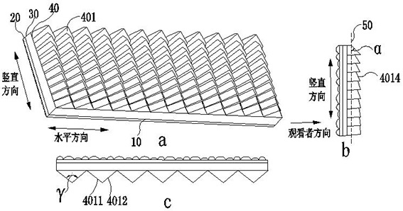
[0056] like image 3 a to 3c are structural schematic diagrams of the optical projection screen 10, wherein image 3 a is a rear oblique view of the optical projection screen 10, image 3 b is a side view of the optical projection screen 10, image 3 c is a top view of the optical projection screen 10 . An optical projection screen 10, comprising a surface layer 20, an imaging layer 30, and a reflective layer 40 arranged in sequence from the viewer's direction, the reflective layer 40 comprising an optical microstructure layer, and the optical microstructure layer is arranged in sequence along the vertical direction of the optical projection screen Several optical microstructure blocks 401 are formed in an array in the horizontal direction of the optical projection screen; each optical microstructure block 401 includes two main reflection surfaces, which are respectively a first main reflection surface 4011 and a second main reflection surface 4012, and the first main reflec...
Embodiment 2
[0071] On the basis of Embodiment 1, it is defined that the optical microstructure block 401 includes three reflective surfaces. like Figure 19 a to 19c are structural schematic diagrams of the optical projection screen 10, wherein Figure 19 a is a rear oblique view of the optical projection screen 10, Figure 19 b is a side view of the optical projection screen 10, Figure 19 c is a top view of the optical projection screen 10 . An optical projection screen 10, comprising a surface layer 20, an imaging layer 30, and a reflective layer 40 arranged in sequence from the viewer's direction, the reflective layer 40 comprising an optical microstructure layer, and the optical microstructure layer is arranged in sequence along the vertical direction of the optical projection screen Several optical microstructure blocks 401 are formed in an array in the horizontal direction of the optical projection screen; each optical microstructure block 401 includes three reflective surfaces,...
Embodiment 3
[0074] like Figure 21 a to 21c are structural schematic diagrams of the optical projection screen 10, wherein Figure 21 a is a rear oblique view of the optical projection screen 10, Figure 21 b is a side view of the optical projection screen 10, Figure 21 c is a top view of the optical projection screen 10 . An optical projection screen 10 includes a surface layer 20, an imaging layer 30, and a reflective layer 40 arranged in sequence along the viewer's direction. The reflective layer includes an optical microstructure layer. The microstructure block 401 is formed in an array in the vertical direction of the optical projection screen. The optical microstructure block 401 includes two main reflection surfaces, which are respectively the first main reflection surface 4011 and the second main reflection surface 4012, and the first main reflection surface 4011 and the second main reflection surface. The intersection line 4014 of the two main reflecting surfaces 4012 in spac...
PUM
 Abstract
Description
Claims
Application Information
 - R&D
- Intellectual Property
- Life Sciences
- Materials
- Tech Scout
- Unparalleled Data Quality
- Higher Quality Content
- 60% Fewer Hallucinations
Browse by: Latest US Patents, China's latest patents, Technical Efficacy Thesaurus, Application Domain, Technology Topic, Popular Technical Reports.
© 2025 PatSnap. All rights reserved.Legal|Privacy policy|Modern Slavery Act Transparency Statement|Sitemap|About US| Contact US: help@patsnap.com