
Cantilever type conveying device

A conveying device, a cantilever-type technology, applied in the direction of conveyor control devices, conveyors, conveyor objects, etc., can solve the problems of space utilization, low work efficiency, and complex structure

Pending Publication Date: 2020-09-04
SUZHOU MAXWELL TECH CO LTD
View PDF0 Cites 2 Cited by
  • Summary
  • Abstract
  • Description
  • Claims
  • Application Information

AI Technical Summary

Problems solved by technology

[0004] Based on this, it is necessary to provide a cantilever conveying device for the problems of complex structure, low space utilization and low work efficiency.

Method used


Image

  • Cantilever type conveying device
  • Cantilever type conveying device
  • Cantilever type conveying device

Examples


Embodiment Construction

[0027] In order to make the above objects, features and advantages of the present invention more comprehensible, specific implementations of the present invention will be described in detail below in conjunction with the accompanying drawings. In the following description, numerous specific details are set forth in order to provide a thorough understanding of the present invention. However, the present invention can be implemented in many other ways different from those described here, and those skilled in the art can make similar improvements without departing from the connotation of the present invention, so the present invention is not limited by the specific embodiments disclosed below.

[0028] In describing the present invention, it should be understood that the terms "center", "longitudinal", "transverse", "length", "width", "thickness", "upper", "lower", "front", " Back", "Left", "Right", "Vertical", "Horizontal", "Top", "Bottom", "Inner", "Outer", "Clockwise", "Counte...


PUM


Abstract

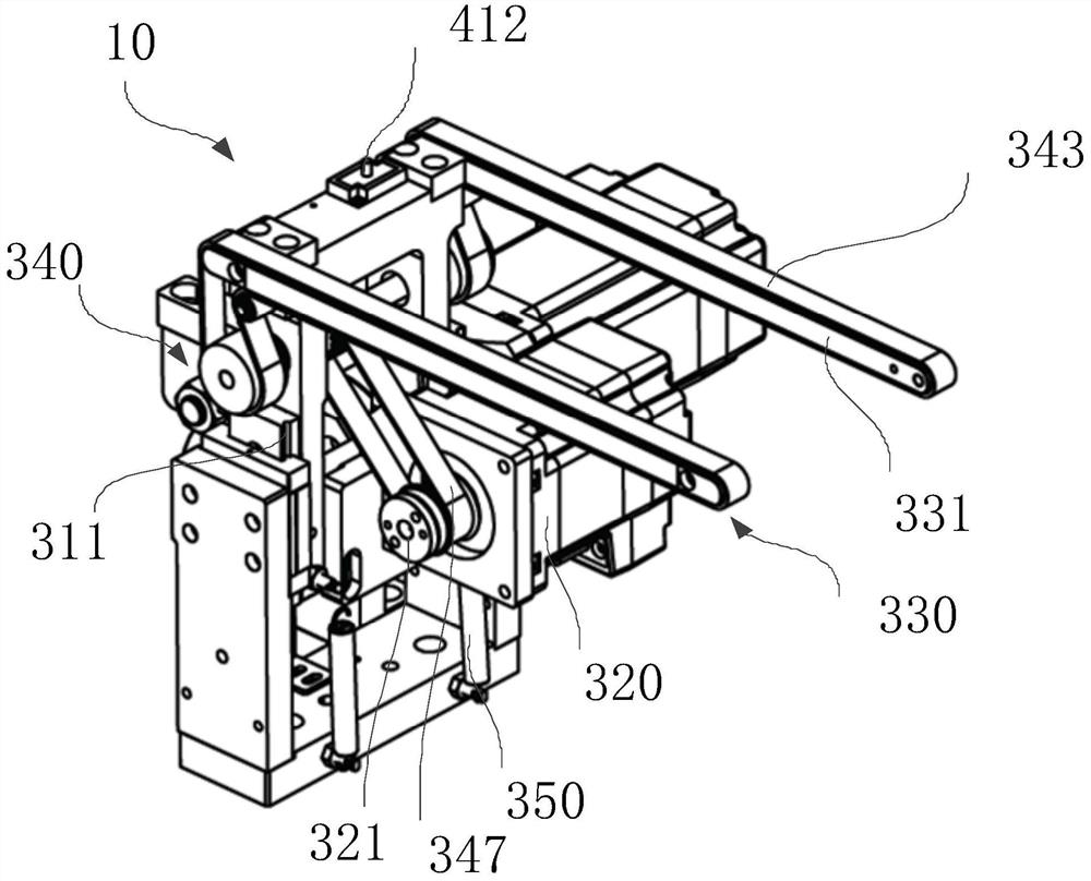
The invention relates to a cantilever type conveying device. The cantilever type conveying device comprises a frame, a cam lifting mechanism and a cantilever type conveying mechanism; the cam liftingmechanism comprises a first driving unit and a cam, wherein the first driving unit is mounted on the frame; the first driving unit is provided with a first horizontal output shaft; the cam is connected with the first horizontal output shaft in a transmission manner; the cantilever type conveying mechanism comprises a bracket and a second driving unit, a transmission unit and two cantilever units,wherein the second driving unit, the transmission unit and the two cantilever units are mounted on the bracket; the bracket is connected with the cam in a matched manner, and the bracket and the cam are mounted on the frame in a slideable manner; the cantilever units comprise cantilever beams; one ends of the cantilever beam are mounted at the end part, far away from the frame, of the bracket; theother ends of the cantilever beams extend out of the bracket; the two cantilever beams are oppositely arranged in a spaced manner; the transmission unit comprises a first transmission shaft, belt wheels and a belt; the first transmission shaft is rotatably mounted on the bracket; the belt wheels are mounted at the two ends of the first transmission shaft; the belt is movably wound on the belt wheels and the cantilever beams; and the second driving unit is provided with a second horizontal output shaft and is connected with the first transmission shaft in a transmission manner.

Description

technical field [0001] The invention relates to the technical field of industrial assembly lines, in particular to a cantilever conveying device. Background technique [0002] With the development of industrial assembly line technology, most of modern industrial production adopts assembly line operation, multiple assembly lines realize the transportation of materials, and cooperate with manipulators to realize the transfer of materials between different assembly lines. [0003] At present, each assembly line includes a driving motor, a support table, a pulley and a belt. The pulley is set at the four corners of the support table and is connected to the drive motor. The belt is set on the pulley and moves under the driving standby to convey For materials, manipulators are set between different assembly lines. The manipulators realize reciprocating operations such as clamping and lifting of materials, horizontal movement, and drop release. However, the structure of the above-m...

Claims


Application Information

Patent Timeline
IPC IPC(8): B65G23/04B65G15/32B65G41/00B65G43/08
CPCB65G15/32B65G23/04B65G41/00B65G43/08
Inventor 洪飞龚志清查俊
Owner SUZHOU MAXWELL TECH CO LTD
Learn More