
Parallel groove clamp processing device with high matching degree

A technology of processing equipment and matching degree, which is applied to other manufacturing equipment/tools, manufacturing tools, clamping/spring connections, etc., can solve problems such as low matching accuracy, easy deviation, and misalignment of arc-shaped grooves 103, so as to improve production Efficiency, good fit, and good fit precision

Active Publication Date: 2020-09-01
宁波奉欣电力金具实业股份有限公司
View PDF6 Cites 0 Cited by
  • Summary
  • Abstract
  • Description
  • Claims
  • Application Information

AI Technical Summary

Problems solved by technology

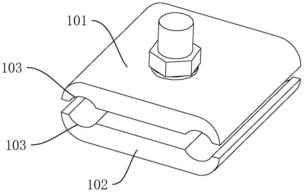
[0004] The above-mentioned existing technical solutions have the following defects: in the production process of the ditch line clamp, the upper and lower aluminum strips are first prepared by extrusion, and then they are respectively cut, drilled, A series of processes such as grinding to obtain the upper clamping block 101 and the lower clamping block 102, and then the upper clamping block 101 and the lower clamping block 103 are connected together by bolts and nuts
Since the upper clamping block 101 and the lower clamping block 102 after punching the hole need to cooperate with each other, so that the two opposite arc-shaped grooves 103 can clamp the wire well, in the process of punching, the upper clamping block 101 and the lower clamping block The position of the hole of 102 is easy to deviate, so that the matching accuracy between the upper clamping block 101 and the lower clamping block 102 is low, so that the arc-shaped groove 103 of the upper clamping block 101 and the lower clamping block 102 often has the problem of misalignment

Method used


Image

  • Parallel groove clamp processing device with high matching degree
  • Parallel groove clamp processing device with high matching degree
  • Parallel groove clamp processing device with high matching degree

Examples


Embodiment

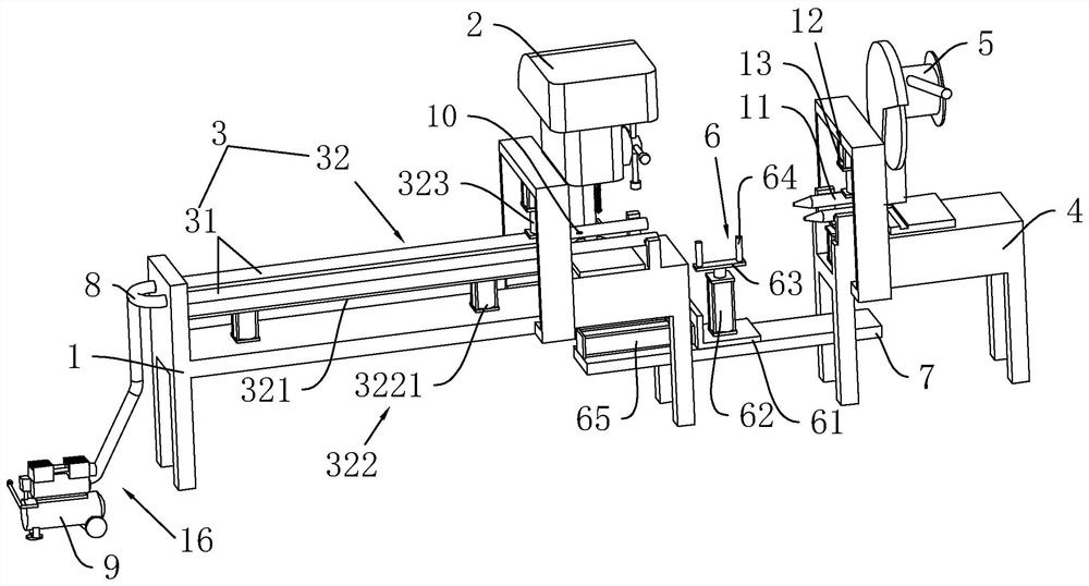
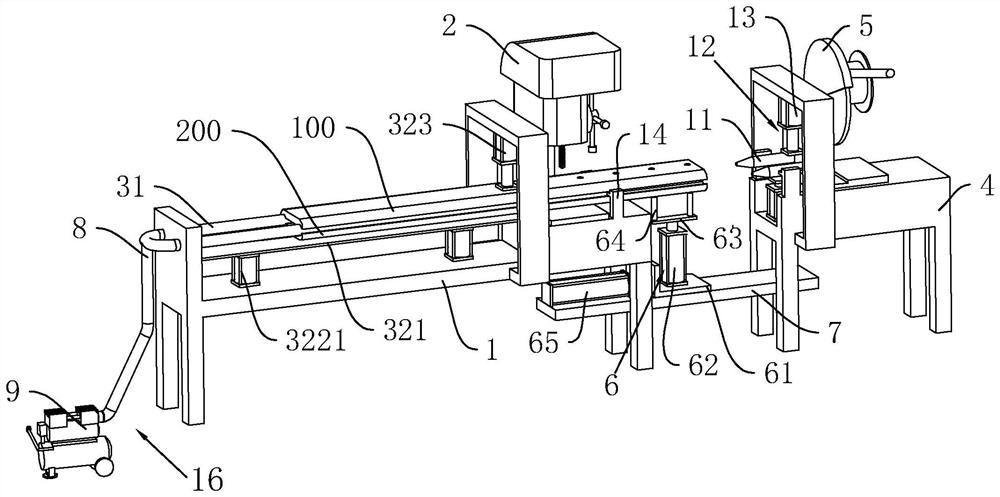
[0035] refer to figure 2 and image 3 , is a high-coordination parallel groove wire clamp processing equipment disclosed in the present invention, which is used for punching and cutting the upper strip 100 and the lower strip 200, including the workbench 1 and the punching machine installed on the workbench 1. Hole machine 2, puncher 2 can select devices such as bench drill for use. A positioning mechanism 3 for clamping the upper strip material 100 and the lower strip material 200 is installed on the workbench 1, so that the upper strip material 100 and the lower strip material 200 are in a coordinated state, and then punched by the punching machine 2, so that The precision of the drilled holes is more accurate, reducing the situation of later repairing holes. One end of the workbench 1 is also equipped with a cutting table 4, on which a cutting machine 5 for cutting the upper strip 100 and the lower strip 200 is installed. A pushing assembly 6 for delivering the upper st...


PUM


Abstract

The invention relates to a parallel groove clamp machining device with high matching degree. The device comprises a workbench and a perforating machine arranged on the workbench, a cutting table is arranged at one side of the workbench, and a cutting machine is arranged on the cutting table. A pushing assembly is arranged between the workbench and the cutting table, the workbench is provided witha positioning mechanism used for positioning an upper strip material and a lower strip material, and the positioning mechanism comprises a positioning rod which is horizontally arranged above the workbench. The positioning mechanism further comprises a clamping assembly used for clamping the upper strip material and the lower strip material to the upper side and the lower side of the positioning rod, the clamping assembly comprises a long plate arranged below the positioning rod and used for supporting the lower strip material, a driving piece used for driving the long plate to ascend and descend is arranged on the workbench, the clamping assembly further comprises a first air cylinder arranged above the positioning rod, and a cooling assembly used for cooling a drill bit of the perforating machine is arranged on the positioning rod. The parallel groove clamp machining device has a high-precision perforating effect.

Description

technical field [0001] The invention relates to the technical field of parallel groove wire clamp preparation, in particular to a parallel groove wire clamp processing equipment with high matching degree. Background technique [0002] Power fittings are metal accessories that connect and combine various devices in the power system to transmit mechanical loads, electrical loads and some kind of protection. Parallel clamps play a very important role in power fittings. Parallel clamps are contact fittings used to connect two parallel wires to transmit electrical loads. They are widely used, such as jumpers for non-linear poles and power systems. T-connection and branch lines at non-load-bearing connections can be completed with parallel trench clamps. [0003] refer to figure 1 , the existing parallel ditch line clamp mainly includes an upper clamping block 101 and a lower clamping block 102, the upper clamping block 101 and the lower clamping block 102 are provided with thro...

Claims


Application Information

Patent Timeline
Patent Type & Authority Applications(China)
IPC IPC(8): H01R43/027B23P23/02H01R4/44
CPCB23P23/02H01R4/44H01R43/027
Inventor 陈志财章晓鸣宋志平施存军陈新军
Owner 宁波奉欣电力金具实业股份有限公司
Learn More