
Modulation depth extraction and compensation method in PGC phase demodulation method

A technology of modulation depth and phase modulation, applied in measurement devices, instruments, optical devices, etc., can solve problems such as difficult real-time compensation, nonlinear errors, etc., to improve the phase measurement accuracy, achieve accurate extraction, and eliminate nonlinear errors. Effect

Active Publication Date: 2020-09-01
ZHEJIANG SCI-TECH UNIV
View PDF5 Cites 2 Cited by
  • Summary
  • Abstract
  • Description
  • Claims
  • Application Information

AI Technical Summary

Problems solved by technology

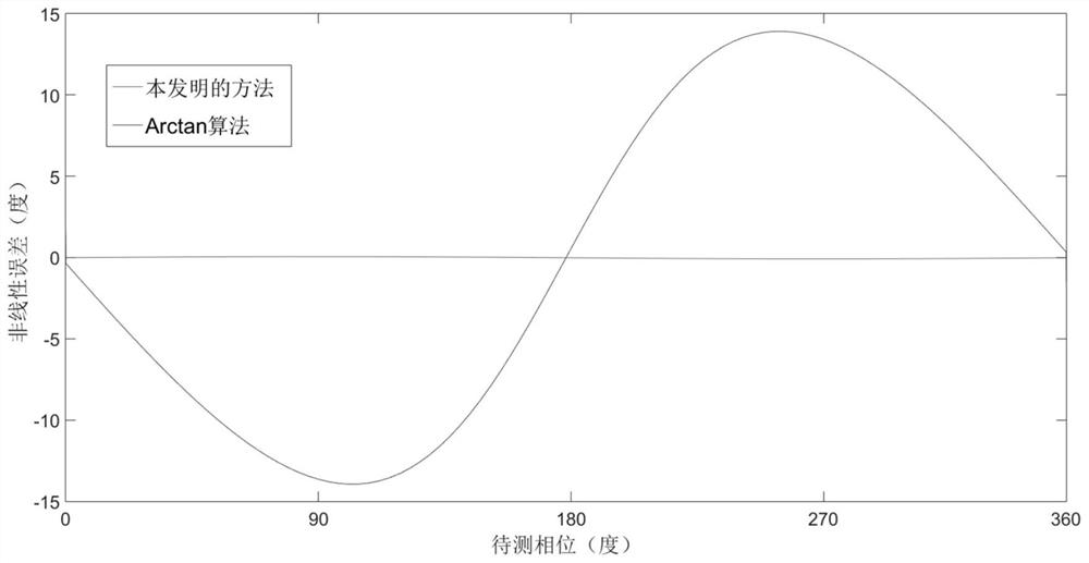
[0004] In order to overcome the deficiencies in the prior art, the present invention discloses a modulation depth extraction and compensation method in the PGC phase demodulation method, which solves the influence of modulation depth fluctuations in PGC demodulation on phase demodulation in real time, and solves the problem of PGC In the phase demodulation technology, the non-linear error caused by the modulation depth fluctuation is difficult to compensate in real time. It has a remarkable effect in the field of measurement of phase sinusoidal changes such as vibration measurement, and improves the accuracy of phase measurement. It can be widely used in interferometric fiber optic sensors, sinusoidal Phase Modulation Interferometry Technology Field

Method used


Image

  • Modulation depth extraction and compensation method in PGC phase demodulation method
  • Modulation depth extraction and compensation method in PGC phase demodulation method
  • Modulation depth extraction and compensation method in PGC phase demodulation method

Examples


Embodiment Construction

[0040] The present invention will be described in detail below in conjunction with the accompanying drawings and embodiments.

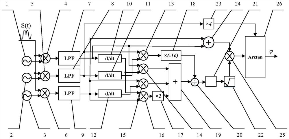
[0041] Such as figure 1As shown, the method adopts the following system, the input terminals of the first multiplier 4, the second multiplier 5, and the third multiplier 6 are all connected to the digital interference signal S(t), the first digital frequency synthesizer 1, the second digital frequency The output terminals of synthesizer 2, the third digital frequency synthesizer 3 are connected to the input terminals of the first multiplier 4, the second multiplier 5 and the third multiplier 6 respectively; The pass filter 7 is connected to the input end of the first differential operator 10, the input end of the fifth multiplier 14 and the input end of the second adder 24 respectively, and the output end of the second multiplier 5 passes through the second low-pass filter After 8, be respectively connected to the input end of the second differential...


PUM


Abstract

The invention discloses a modulation depth extraction and compensation method in a PGC phase demodulation method. The method comprises the steps: multiplying filtered, amplified and analog-digital sampled interference signals by reference signals of a first-order harmonic, a second-order harmonic and a third-order harmonic respectively, performing low-pass filtering to obtain three harmonic amplitude signals, performing differential operation on the three harmonic amplitude signals to obtain three harmonic differential signals, and solving modulation depth by using the harmonic amplitude signals and the harmonic differential signals; in combination with a Bessel function recursion formula, constructing a new harmonic amplitude signal which is not influenced by the modulation depth throughthe harmonic amplitude signal and the solved modulation depth value, so that the influence of the modulation depth is eliminated; and finally, accurately solving the phase to be measured through arc tangent operation. According to the method, the problem that nonlinear errors are difficult to compensate in real time due to modulation depth fluctuation in the PGC phase demodulation technology is solved, the phase measurement precision is improved, and the method can be widely applied to the technical field of interferometric optical fiber sensors and sinusoidal phase modulation interference.

Description

technical field [0001] The invention relates to the technical field of phase-generated carrier (PGC) demodulation, in particular to a method for extracting and compensating modulation depth in the PGC phase demodulation method. Background technique [0002] Phase-generated carrier (PGC) demodulation technology is widely used in interferometric fiber optic sensors and sinusoidal phase modulation interferometers due to its advantages of low-frequency interference resistance, high sensitivity, and large dynamic range. PGC demodulation technology mainly includes differential cross multiplication algorithm (PGC-DCM) and arctangent algorithm (PGC-Arctan). The PGC-DCM method obtains the phase to be measured by performing differential cross multiplication and integration operations on the quadrature components. The measurement results of this method are easily affected by fluctuations in laser light intensity, carrier phase delay, and modulation depth. The PGC-Arctan method obtains...

Claims


Application Information

Patent Timeline
IPC IPC(8): G01B9/02
CPCG01B9/0201G01B9/02055
Inventor 严利平陈本永张倚得谢建东
Owner ZHEJIANG SCI-TECH UNIV
Learn More