
Liquefaction unit in vehicle-mounted mobile oilfield vent gas recovery system and liquefaction method thereof

A recovery system and air release technology, which is applied in the recovery of liquid hydrocarbon mixtures and the petroleum industry, can solve problems such as instability, waste of resources, and poor economy, and achieve the effects of reducing height, reducing emissions, and improving product recovery.

Active Publication Date: 2020-09-01
WUXI HONGSHENG HEAT EXCHANGER MANUFACTURING CO LTD
View PDF4 Cites 3 Cited by
  • Summary
  • Abstract
  • Description
  • Claims
  • Application Information

AI Technical Summary

Problems solved by technology

Because the air released from oil fields is relatively scattered, the gas volume is small and unstable, and conventional pipeline transportation is used, the investment cost is high and the economy is poor. Therefore, most of the air released from oil fields is directly discharged and burned, which not only wastes resources, but also causes environmental pollution, which is not in line with the national standard Safety and environmental requirements
[0003] At present, there are related recovery systems designed at home and abroad to recycle oilfield air, such as the patent with the authorized announcement number CN209872346U: a separation and synthesis device for realizing the in-situ conversion of oilfield associated gas, which is used for desulfurization of oilfield associated gas , conversion and separation to obtain CO, hydrogen and synthesis gas, but this device is not suitable for recovering mixed hydrocarbons and liquefied natural gas in the oil field vent air, and the liquefaction effect of recovering mixed hydrocarbons and liquefied natural gas from oil field vent air is not good, so Affect the quality of liquefied products, therefore, it is necessary to design a liquefaction unit and method in a vehicle-mounted mobile oilfield vent air recovery system with good liquefaction effect

Method used


Image

  • Liquefaction unit in vehicle-mounted mobile oilfield vent gas recovery system and liquefaction method thereof

Examples


Embodiment Construction

[0024] The present invention will be further described in detail below in conjunction with the accompanying drawings and examples. The following examples are explanations of the present invention and the present invention is not limited to the following examples.

[0025] Example.

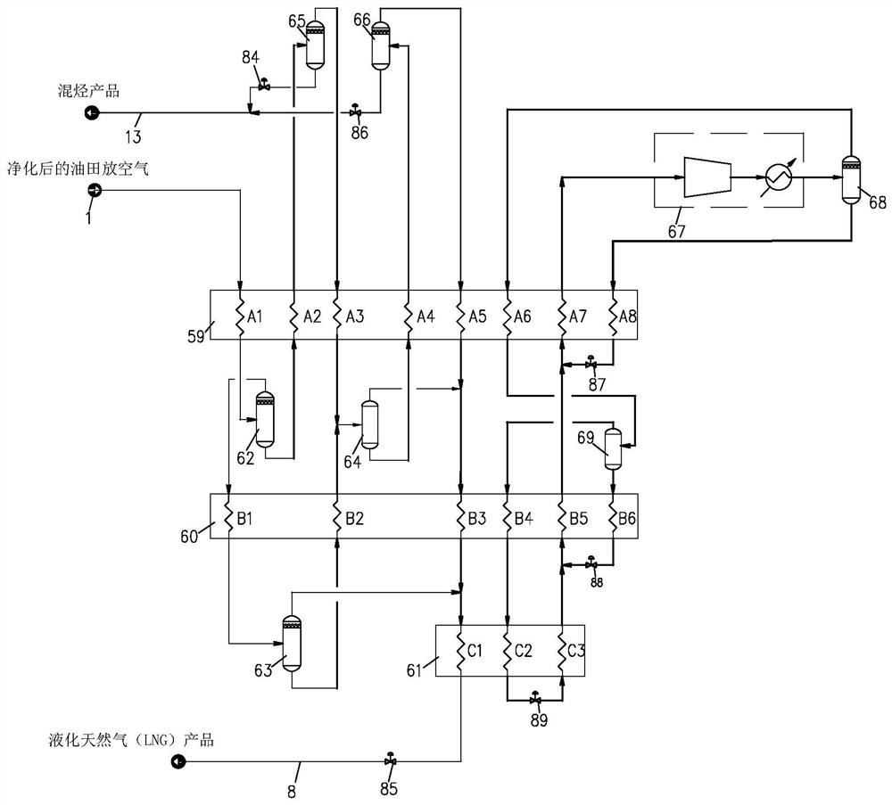
[0026] see figure 1 , figure 1Shown is the liquefaction unit in the vehicle-mounted mobile oilfield release air recovery system. The vehicle-mounted mobile oil field release air recovery system is used to recover mixed hydrocarbons and liquefied natural gas products, including two units: a purification unit and a liquefaction unit.

[0027] The liquefaction unit in this embodiment includes a precooling heat exchanger 59, a cryogenic heat exchanger 60, a liquefaction heat exchanger 61, a primary separator 62, a secondary separator 63, a tertiary separator 64, a normal temperature separator 65, a mixing Hydrocarbon separator 66 and closed mixed refrigerant three-stage throttling refrigeration devi...


PUM


Abstract

The invention relates to a liquefaction unit in a vehicle-mounted mobile oilfield vent gas recovery system and a liquefaction method thereof. The liquefaction unit comprises a precooling heat exchanger, a cryogenic heat exchanger, a liquefaction heat exchanger, a first-stage separator, a second-stage separator, a third-stage separator, a normal-temperature separator, a mixed hydrocarbon separatorand a closed mixed refrigerant three-stage throttling refrigeration device. A bottom liquid outlet of the mixed hydrocarbon separator is connected with a mixed hydrocarbon product conveying pipeline.The closed mixed refrigerant three-stage throttling refrigeration device provides cooling capacity for the pre-cooling heat exchanger, the cryogenic heat exchanger and the liquefaction heat exchanger.The liquefaction unit adopts the first-stage separator, the second-stage separator, the third-stage separator, the normal-temperature separator and the mixed hydrocarbon separator to separate a liquid mixed hydrocarbon product and a liquid natural gas product. The product recovery rate is increased, the emission of oilfield vent gas is reduced, a traditional mixed hydrocarbon recovery rectifyingtower is canceled, the height of low-temperature equipment is reduced, and the design, manufacturing and application of a vehicle-mounted mobile low-temperature cold box skid are realized.

Description

technical field [0001] The invention relates to the technical field of processing oilfield air, in particular to a liquefaction unit and a liquefaction method in a vehicle-mounted mobile oilfield air recovery system. Background technique [0002] Oil field vent air refers to the vent gas rich in methane, ethane, propane and other hydrocarbons produced during the oil production process, and it is a resource that can be recycled. Because the air released from oil fields is relatively scattered, the gas volume is small and unstable, and conventional pipeline transportation is used, the investment cost is high and the economy is poor. Therefore, most of the air released from oil fields is directly discharged and burned, which not only wastes resources, but also causes environmental pollution, which is not in line with the national standard Safety and environmental requirements. [0003] At present, there are related recovery systems designed at home and abroad to recycle oilfie...

Claims


Application Information

Patent Timeline
Patent Type & Authority Applications(China)
IPC IPC(8): C10G5/00C10G5/06
CPCC10G5/00C10G5/06
Inventor 周燊王萌王庭宁陈志伟
Owner WUXI HONGSHENG HEAT EXCHANGER MANUFACTURING CO LTD
Learn More