Clamping device for thin plate compression experiment

A clamping device and experimental technology, applied in the direction of workpiece clamping devices, manufacturing tools, etc., can solve the problem that the cyclic loading of thin plate tension-compression cannot be realized, continuous tension-compression experiments of thin plates cannot be carried out, and large deformation cannot be carried out Compression and other issues, to achieve the effect of good promotion and use value, convenient strain collection, and simple structure

Pending Publication Date: 2020-09-01
TANGSHAN IRON & STEEL GROUP +1
View PDF2 Cites 5 Cited by
  • Summary
  • Abstract
  • Description
  • Claims
  • Application Information

AI Technical Summary

Problems solved by technology

[0003] Chen Jinrong (Chen Jinrong, Compression Experiments on Metal Sheets, Acta Mechanics, 1981, Phase II: 173-179) proposed a clamping device in which the compressed sample is clamped by two flat plates with high stiffness, but the device cannot Compression with a large amount of deformation, and continuous tension-compression experiments on thin plates cannot be carried out
[0004] Chinese Patent Application No. CN 103257075 A discloses "A Clamping Device for Preventing In-Plane Compression Instability of Thin Plates". Although this clamping device can realize the tension-compression cycle experiment of thin plates, in order to avoid the influence of friction, The force application area is mainly in the non-gauge length section. The pressure in the gauge length section of the sample is transmitted through the comb structure. The pressure is not large, and the risk of buckling of the sample in the gauge length section is great, and its strain measurement is very inconvenient.
[0005] Chinese Patent Application No. CN 107727489 A discloses "A Clamping and Fixing Device for Compressing a Metal Sheet". Although there are strain measurement holes, in order to prevent the sample from buckling, the clamping block covers almost all of the sample, and the thin plate cannot be clamped. Tensile-compressive cyclic loading
[0006] To sum up, the current devices for compression experiments on thin plates have certain defects, and cannot complete the thin plate compression and tension-compression experiments well, and need to be improved urgently.

Method used


Image

  • Clamping device for thin plate compression experiment
  • Clamping device for thin plate compression experiment
  • Clamping device for thin plate compression experiment

Examples


Embodiment Construction

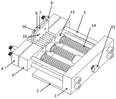
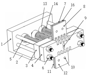
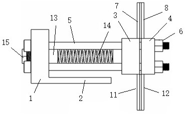
[0024] The present invention consists of clamping support plate 1, bottom plate 2, rear sample splint 3, front sample splint 4, screw rod 5, nut 6, rear upper groove splint 7, front upper groove splint 8, strain measurement hole 9, screw Column 10, rear lower grooved splint 11, front lower grooved splint 12, spring seat 13, spring 14, spring bolt 15 form.

[0025] Figure 1-5 It is shown that the clamping support plate 1 and the base plate 2 form an L-shaped structure, the clamping support plate 1 is placed vertically, the base plate 2 is in a horizontal position, and the base plate 2 is connected to the lower end of the clamping support plate 1 .

[0026] Figure 1-5 It shows that the front sample splint 4 and the rear sample splint 3 are respectively the same rectangular plate, the front sample splint 4 and the rear sample splint 3 are parallel and opposite, and the sample 16 is placed on the front sample splint 4 and the rear sample splint 3 between. The rear sample spli...


PUM


Abstract

The invention discloses a clamping device for a thin plate compression experiment, which belongs to the technical field of plate forming test equipment and is used for clamping a thin plate of a compression experiment. The technical scheme is as follows: the middle of a sample is placed between a front sample clamping plate and a rear sample clamping plate; a strain measuring hole opposite to themiddle of the sample is arranged on the plate surface of the front sample clamping plate; a screw rod connects a clamping support plate with the front sample clamping plate and the rear sample clamping plate by nuts; the two ends of a spring are separately embedded in the spring seat between the clamping support plate and the rear sample clamping plate; the front sample clamping plate is connectedto a front upper groove shape clamping plate and a front lower groove shape clamping plate respectively; the rear sample clamping plate is connected to a rear upper groove shape clamping plate and arear lower groove shape clamping plate respectively; and the upper and lower parts of the sample are placed between the front upper groove shape clamping plate, the rear upper groove shape clamping plate and the front lower groove shape clamping plate and the rear lower groove shape clamping plate. The clamping device for the thin plate compression experiment has a simple structure and high test accuracy, can facilitate strain collection, and can complete all experiments of compression and tension-compression cyclic loading of thin plates with different strength levels and thicknesses.

Description

technical field [0001] The invention discloses a clamping device for thin plate compression, which belongs to the technical field of plate forming test equipment. Background technique [0002] Stamping is an important process in the field of material processing, and occupies an important position in the automotive industry, aerospace, shipbuilding and other processing and manufacturing industries. Among them, the performance of the sheet is an important basis for determining the parameters of the forming process. Especially in recent years, with the continuous improvement of lightweight and safety performance requirements, the application proportion of high-strength sheets has increased, and the rebound characteristics of the sheets have increased significantly. Therefore, by obtaining the material's It is very necessary to understand the influence of the Bauschinger effect of the material on the stamping process and springback through parameters such as compressive strength...

Claims


Application Information

Patent Timeline
IPC IPC(8): B25B11/00
CPCB25B11/00
Inventor 张茜杜雁冰吕浩齐建群牛星辉李立铭王秋雨张赛娟刘淑影
Owner TANGSHAN IRON & STEEL GROUP
Why Eureka
Try Eureka