A machining cutting fluid filter device
A filter device and mechanical processing technology, which is applied in the direction of filtration treatment, metal processing equipment, metal processing machinery parts, etc., can solve the problems of cutting fluid overflowing the outside of the material tank, small return hole diameter, easy to be covered by chips, etc., to achieve suitable Promote the use, meet the filtering needs, and the effect of simple structure
- Summary
- Abstract
- Description
- Claims
- Application Information
AI Technical Summary
Problems solved by technology
Method used
Image

Examples
Embodiment 1
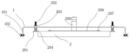
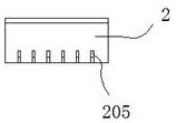
[0047] A cutting fluid filtering device for machining, including a bracket 1, the bracket 1 is made of bent metal plate (aluminum or steel), the two ends of the bracket 1 are bent downward to form a side plate part 101, and the side plate part 101 is formed on the side A screw 102 is screwed into the outside of the plate part 101. After the screw 102 is screwed in, it resists the material trough for collecting chips. A box body 2 is arranged inside the bracket 1, and horizontal bars are arranged on both sides of the box body 2. Ear plate 201, a rod 202 is welded on the top of the ear plate 201, the upper end of the rod 202 passes through the bracket 1 upwards, and the rod 202 can slide vertically along the bracket 1, the rod The member 202 passes upwardly through the bracket 1 and is fitted with a nut 203. A spring 204 is sheathed on the rod member 202, and the spring 204 acts between the bracket 1 and the box body 2. A plurality of liquid inlet grooves 205 are arranged at two...
Embodiment 2
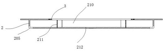
[0049] A gasket 3 is disposed on the upper end of the box body 2 , and the gasket 3 is clamped by the cover plate 206 and the box body 2 .
Embodiment 3
[0051] A groove 221 is provided at the bottom of the cover plate 206, and a plurality of T-shaped sliding grooves 222 are arranged on the side of the groove 221 away from the concave hole 212, and a magnetic The steel plate 223, the magnetic steel plate 223 has a plurality of arc-shaped grooves 224, when two adjacent magnetic steel plates 223 are arranged in the same direction, the adjacent grooves 224 are combined to form a gap through which the cooling liquid passes 225, when two adjacent magnetic steel plates 223 are reversed, a circular passing hole 226 is formed between adjacent grooves 224, and the upper end of the magnetic steel plate 223 has a T-shaped slider 227 , the slider 227 cooperates with the chute 222; a plurality of the magnetic steel plates 223 are located inside the inner frame 210; the magnetic steel plates 223 slide along the chute 222 to the groove 221 for Take it out downward; the installation direction of the magnetic steel plate 223 can be adjusted. Wh...
PUM
| Property | Measurement | Unit |
|---|---|---|
| porosity | aaaaa | aaaaa |
| diameter | aaaaa | aaaaa |
Abstract
Description
Claims
Application Information
 - R&D
- Intellectual Property
- Life Sciences
- Materials
- Tech Scout
- Unparalleled Data Quality
- Higher Quality Content
- 60% Fewer Hallucinations
Browse by: Latest US Patents, China's latest patents, Technical Efficacy Thesaurus, Application Domain, Technology Topic, Popular Technical Reports.
© 2025 PatSnap. All rights reserved.Legal|Privacy policy|Modern Slavery Act Transparency Statement|Sitemap|About US| Contact US: help@patsnap.com