
A multi-standard glass door tooling

A glass door, multi-specification technology, used in workbenches, manufacturing tools, hand-held tools, etc., can solve the problems of no correction device, poor assembly reliability, product specification limitations, etc., to reduce defects, high assembly accuracy, and versatility. strong effect

Active Publication Date: 2017-05-31
ZHEJIANG SANXING NEW MATERIALS
View PDF7 Cites 0 Cited by
  • Summary
  • Abstract
  • Description
  • Claims
  • Application Information

AI Technical Summary

Problems solved by technology

However, in the actual production process, the above-mentioned technical solution has the following disadvantages: First, the pushing mechanism exerts force on the four corners of the flat glass. Quality problems; second, the right-angle assembly mechanism is fixed, so the product specifications that can be assembled are relatively limited; third, when the frame bends, there is no matching correction device, so the assembly reliability is poor

Method used


Image

  • A multi-standard glass door tooling
  • A multi-standard glass door tooling
  • A multi-standard glass door tooling

Examples


Embodiment 1

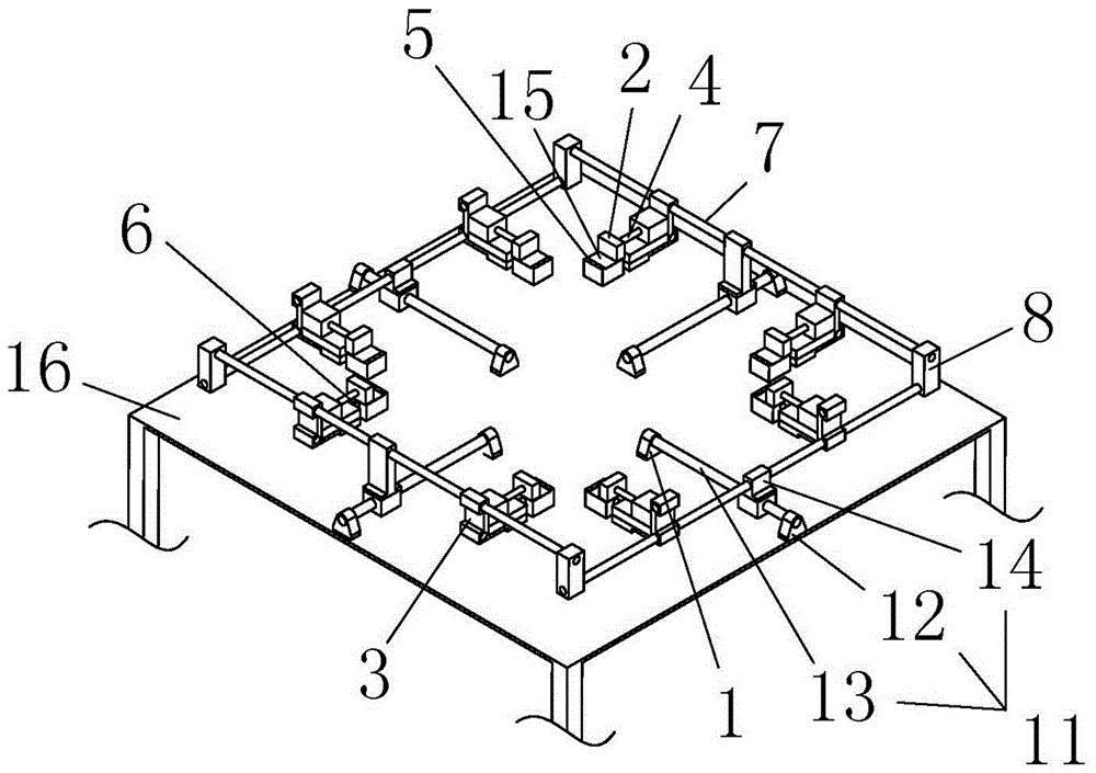
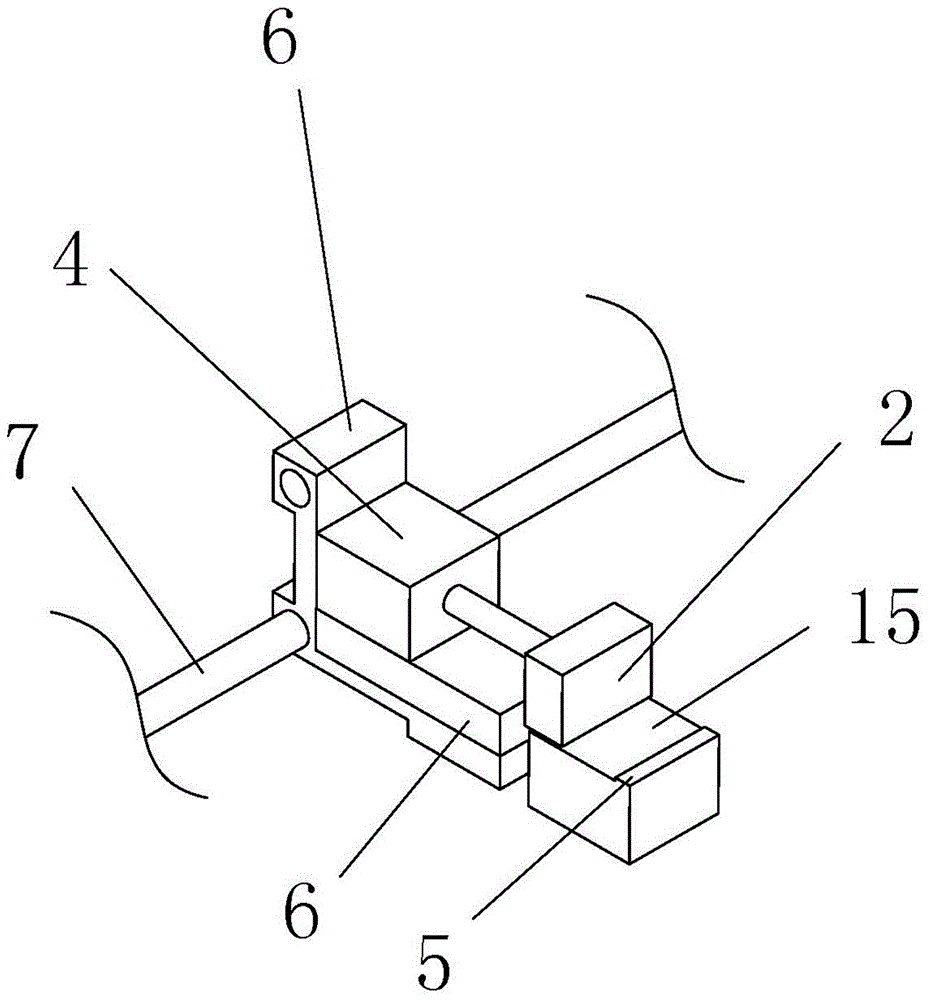
[0034] Embodiment 1: as figure 1As shown, a multi-standard glass door tooling is used for assembling the flat glass of the door frame to make an embedded glass frame door, including a flat glass support part 1 for placing the flat glass, and a flat glass support part 1 arranged on the flat glass The surrounding frame support part 15 that makes the door frame and the flat glass be placed on the same plane also includes a frame support part 15 that is arranged on one side of the frame support part 15 and abuts against the door frame from the outside and makes it point to the displacement of the flat glass to make the door A fastening mechanism with the frame nested around the plate glass, and a correction mechanism that abuts against the inner side of the door frame and makes the door frame move away from the plate glass after the fastening mechanism completes the displacement or movement tendency.

[0035] Such as figure 2 As shown, the fastening mechanism includes a fastenin...

Embodiment 2

[0039] Embodiment 2: The difference between Embodiment 5 and Embodiment 1 is that the guide rail 7 is fixed end-to-end through fixed connectors, and the length of the air rods of the first pneumatic device 4 and the second pneumatic device 6 is used to adjust the fastening structure and the correction mechanism working position; no workbench base 11 is provided.

Embodiment 3

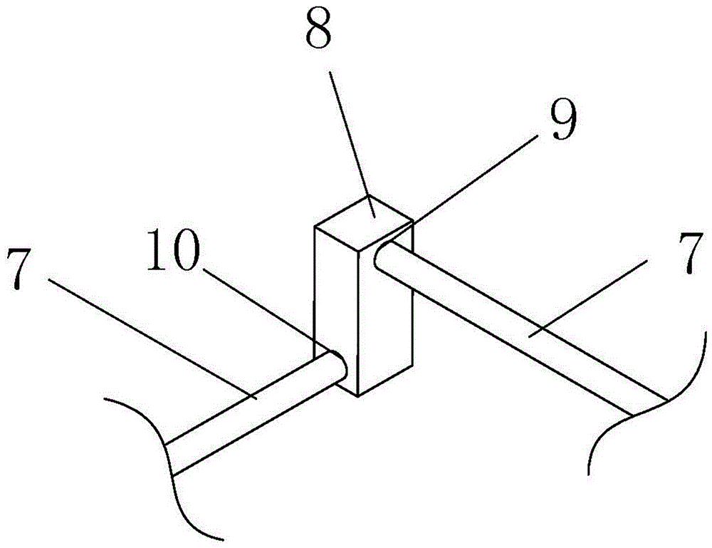
[0040] Embodiment 3: The difference between Embodiment 3 and Embodiment 1 is that the adjustment component 8 is placed directly on the workbench top 16; the fastening structure and the correction mechanism are arranged alternately.


PUM


Abstract

The application discloses a multi-specification glass door tool which is used for assembling plate glass of a door framework to manufacture an embedded type glass framework door. The multi-specification glass door tool comprises a plate glass supporting part for storing plate glass, a framework supporting part, a fastening mechanism and a correcting mechanism, wherein the framework supporting part is arranged at the periphery of the plate glass supporting part and is used for enabling the door framework and the plate glass to be arranged on the same plane; the fastening mechanism is arranged on one side of the framework supporting part and leans against the door framework from the outer side to enable the door framework to generate displacement pointing to the plate glass so that the door framework is embedded into the periphery of the plate glass; and after the displacement is finished by the fastening mechanism, the correcting mechanism enables the door framework to generate displacement or movement tendency deviating from the plate glass by leaning against the inner side of the door framework. By positioning the plate glass and the framework, primary pre-assembling is realized; fastening is realized by applying a force to the outer side to extrude the framework; correction is realized by applying a force to the inner side to pull the framework; and therefore, fastening and straight automatic assembling of the framework and the plate glass are realized.

Description

technical field [0001] The invention relates to the field of frame door assembly devices, in particular to a multi-standard glass door tooling. Background technique [0002] Embedded glass frame doors and windows are commonly used door and window structures, which are assembled by embedding glass into the frame structure. The existing assembly steps are to first align the flat glass with the door and window frame for pre-installation; then adjust the seam by knocking on the outside of the frame so that the flat glass is completely embedded in the frame; since the assembly is all done by manpower, during the seam adjustment process The unevenness of the knocking force will cause the frame to bend, so in the end it is necessary to adjust the straightness of the frame by touching against the backing and knocking from the inside of the frame. The existing assembly process requires at least two people to complete the above three steps in sequence, which is time-consuming and lab...

Claims


Application Information

Patent Timeline
Patent Type & Authority Patents(China)
IPC IPC(8): B25H1/10B25B27/00
CPCB25B27/00B25H1/10
Inventor 杨敏张金珠沈飞华杨富强刘杰杨玉敏
Owner ZHEJIANG SANXING NEW MATERIALS
Learn More