
Intelligent back pressure type energy-saving flushing valve

A smart anti-pressure and flush valve technology, applied in the field of sanitary products, can solve the problems of low structure utilization optimization rate, narrow application range, and increased use burden, so as to improve the structure utilization optimization rate and avoid excessive flushing noise. Large, to avoid the effect of excessive flushing

Pending Publication Date: 2020-08-28
GUANGDONG SIFEI AOBOTAI INTELLIGENT SANITARY WARE TECH CO LTD
View PDF0 Cites 0 Cited by
  • Summary
  • Abstract
  • Description
  • Claims
  • Application Information

AI Technical Summary

Problems solved by technology

[0003] The existing smart toilet flush valves have the following disadvantages during use: 1. The valve body is large in size, requiring two valve bodies to be combined, and its structure utilization optimization rate is low; 2. Traditional smart toilet flush valves have high requirements for water quality , the scope of application is narrow; 3. The existing intelligent toilet flush valve has the problems of unstable flow and large noise during operation; 4. The valve chip of the flush valve is made of traditional materials, and its service life is low. 5. The internal filter of the flush valve needs to be cleaned regularly, which is time-consuming and laborious, and increases the burden of use. Therefore, we propose a smart back pressure energy-saving flush valve

Method used


Image

  • Intelligent back pressure type energy-saving flushing valve
  • Intelligent back pressure type energy-saving flushing valve
  • Intelligent back pressure type energy-saving flushing valve

Examples


Embodiment Construction

[0027] The present invention will be further described in detail below in conjunction with the accompanying drawings and specific embodiments.

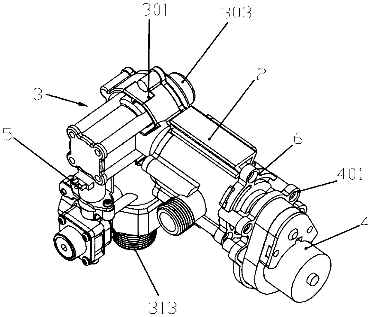
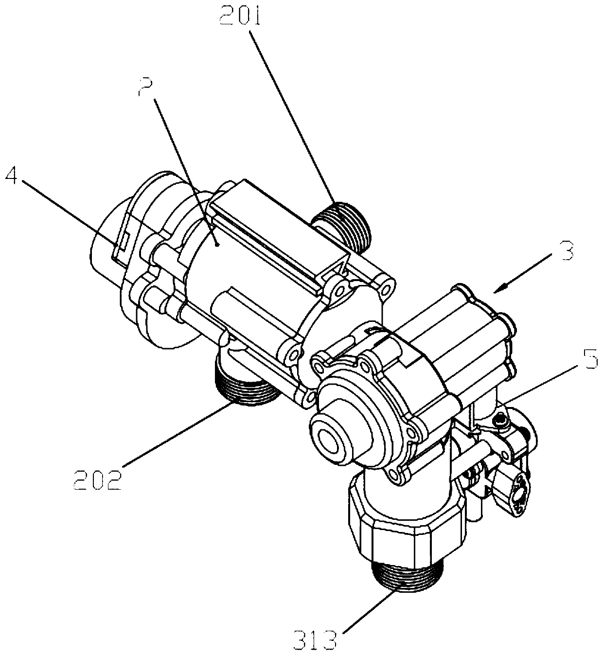
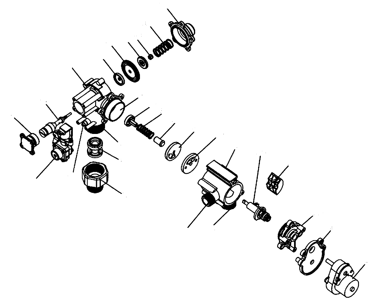
[0028] In this embodiment, refer to Figure 1 to Figure 6 , an embodiment of the present invention, an intelligent anti-pressure energy-saving flush valve, the flush valve is installed inside the toilet 1, the flush valve includes a flush valve body 2, a motor 4, a solenoid valve 5 and a constant Pressure valve 3, the constant pressure valve 3 includes a four-way water inlet connection elbow 301, a gland 302 and an end cover 303, the inside of the four-way water inlet connection elbow 301 has an assembly space, and a valve is installed in the assembly space Stem 304, the head end of the valve stem 304 is installed in the four-way water inlet connection elbow 301 through the gland 302, and the valve stem 304 is provided with a lower pressing piece 305, a diaphragm 306, an upper pressing piece 307, a nut 308 and a spring 309, the lower...


PUM


Abstract

The invention discloses an intelligent back pressure type energy-saving flushing valve, and belongs to the technical field of bathroom accessories. The flushing valve comprises a flushing valve main body, a motor, an electromagnetic valve and a constant pressure valve, wherein the constant pressure valve comprises a four-way water inlet connecting elbow, a gland and an end cover, an assembly spaceis formed in the four-way water inlet connecting elbow, a valve rod is installed in the assembly space, the head end of the valve rod is installed in the four-way water inlet connecting elbow throughthe gland, a lower pressing piece, a membrane, an upper pressing piece, a nut and a spring are sequentially arranged on the valve rod, a containing cavity is formed between the flushing valve main body and a valve body positioning water sealing cover, and a flushing valve assembly is arranged in the containing cavity. The size of the valve body is reduced, the installation is convenient, the flushing valve is suitable for different water qualities, the flow stability of the flushing valve in the operation process is kept, then noise pollution is reduced, meanwhile, the service lives of valvecore pieces are prolonged by adopting novel ceramic piece valve cores, in addition, a filter screen can be automatically washed, and thus the use convenience of the flushing valve is improved.

Description

technical field [0001] The invention relates to the technical field of sanitary products, in particular to an intelligent anti-pressure energy-saving flush valve. Background technique [0002] Smart flush toilets have become a necessity in society in daily life, but with the use of resources by social needs, resources are also decreasing with the development of society, and the various functional conditions of smart flush toilets are A very large system, the flush valve is one of the important components in the smart flush toilet. [0003] The existing smart toilet flush valves have the following disadvantages during use: 1. The valve body is large in size, requiring two valve bodies to be combined, and its structure utilization optimization rate is low; 2. Traditional smart toilet flush valves have high requirements for water quality , the scope of application is narrow; 3. The existing intelligent toilet flush valve has the problems of unstable flow and large noise during...

Claims


Application Information

Patent Timeline
Patent Type & Authority Applications(China)
IPC IPC(8): F16K11/24F16K11/085F16K3/08F16K3/314F16K17/32E03D9/08B01D29/03B01D35/02
CPCB01D29/03B01D35/02E03D9/08F16K3/085F16K3/314F16K11/085F16K11/24F16K17/32
Inventor 谭汉枝
Owner GUANGDONG SIFEI AOBOTAI INTELLIGENT SANITARY WARE TECH CO LTD
Learn More