A sand and gravel separator

A technology for a sand and gravel separator and a shell, which is applied in the field of sand and gravel separators, can solve the problems of high viscosity of slurry and water, low separation rate, and insufficient water separation, so as to improve porosity, water permeability, and sand water. The effect of separation efficiency

Inactive Publication Date: 2021-06-22
杭州金鼎实业有限公司
View PDF1 Cites 0 Cited by
  • Summary
  • Abstract
  • Description
  • Claims
  • Application Information

AI Technical Summary

Problems solved by technology

[0005] The above existing technical solutions have the following defects: the prior art adopts the integrated design of sand screening and sand dehydration, and the sand and slurry water directly enter the drum. Due to the high viscosity of the slurry water, the sand, stone, and cement Slurry-water separation is not thorough enough and the separation rate is low

Method used


Image

  • A sand and gravel separator
  • A sand and gravel separator
  • A sand and gravel separator

Examples


Embodiment Construction

[0038] The present invention will be described in further detail below in conjunction with the accompanying drawings.

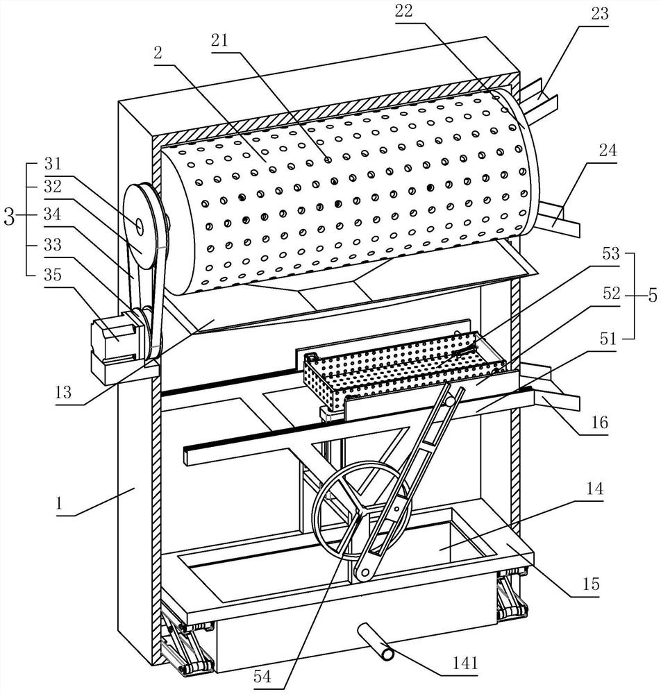
[0039] refer to figure 1 , is a kind of sand and gravel separator disclosed by the present invention, which includes a shell 1, a drum 2 which is rotatably connected to the shell 1 around its own axis and has an opening at one end, a first drive assembly 3 for driving the drum 2 to rotate, and a fixed connection The sealing plate 22 is connected to the casing 1 and rotatably connected to the end of the drum 2 with an opening. The sealing plate 22 is provided with a feed hopper 23 and a stone discharge hopper 24 located below the feed hopper 23, the side wall of the drum 2 is provided with a first sieve hole 21 for sand to pass through, and the inner wall of the drum 2 is provided with a screw pusher. leaves (not shown).

[0040] refer to figure 1 , figure 2 The first drive assembly 3 includes a rotating shaft 31 coaxially fixedly connected to the end fac...


PUM


Abstract

The invention relates to a sand and gravel separator, comprising a shell, a drum rotatably connected to the shell with an opening at one end, a first driving assembly for driving the drum to rotate, and one end fixedly connected to the shell and rotatably connected to the drum with an opening The sealing plate is equipped with a feed hopper and a stone discharge hopper below the feed hopper. The side wall of the drum is provided with a first sieve hole for sand to pass through. The inner wall of the drum is provided with a spiral pusher blade. The body is provided with a diversion groove located under the drum, a sand dewatering mechanism located under the diversion groove, and a slurry receiving tank located below the sand dewatering mechanism. The sand dewatering mechanism includes supports respectively located on both sides of the slurry receiving tank. The frame, the sliding part connected to the support frame by sliding in the horizontal direction, the sieving trough installed on the sliding part and the second drive assembly that drives the sliding part to move back and forth. hole. The invention has the effect of improving the separation rate of sand, stone and cement slurry water.

Description

technical field [0001] The invention relates to the technical field of concrete processing, in particular to a sand and gravel separator. Background technique [0002] The commercial concrete mixing station inevitably produces a large amount of wastewater during the cleaning process of the commercial concrete transport vehicle. This wastewater not only contains conventional building materials such as sand and cement, but also contains various types of concrete additives. If it is discharged directly, it will not only cause a waste of building material resources, but also cause serious pollution to the natural environment. Most of the current cleaning wastewater of concrete mixing plants adopts multi-stage slag separation and natural precipitation method for solid-liquid separation. Not only is the treatment efficiency low, but also the settled wastewater cannot be recycled due to the high content of suspended solids. [0003] In recent years, the commercial concrete mixing ...

Claims


Application Information

Patent Timeline
Patent Type & Authority Patents(China)
IPC IPC(8): B07B1/24B07B1/55B01D33/11B01D33/68
CPCB01D33/11B01D33/68B07B1/24B07B1/55B07B2230/01
Inventor 黄建康高加王志刚陈立峰
Owner 杭州金鼎实业有限公司
Why Eureka
Try Eureka