System and method for switching cycle-by-switching peak current limiting of dc-ac converter

A DC-AC, peak current technology, applied in the field of DC-AC converter switching cycle-by-cycle peak current limiting system, can solve problems such as difficulty in achieving peak current limiting, achieve stable operation, fast response speed, and prevent excessive The effect of the inrush current

Active Publication Date: 2021-07-27
XIAN ACTIONPOWER ELECTRIC
View PDF5 Cites 0 Cited by
  • Summary
  • Abstract
  • Description
  • Claims
  • Application Information

AI Technical Summary

Problems solved by technology

[0003] Aiming at the problem that the DC-AC converter in the prior art is difficult to realize peak current limiting, the present invention proposes a DC-AC converter switching cycle-by-switching peak current limiting system and method, adopts an analog circuit, has fast response speed, and adds slope compensation unit to eliminate subharmonic oscillation

Method used


Image

  • System and method for switching cycle-by-switching peak current limiting of dc-ac converter
  • System and method for switching cycle-by-switching peak current limiting of dc-ac converter
  • System and method for switching cycle-by-switching peak current limiting of dc-ac converter

Examples


Embodiment 1

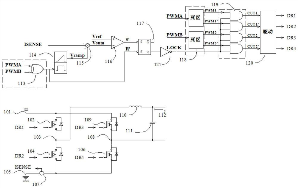
[0086] figure 1 A schematic diagram of the switching cycle-by-switching peak current limiting system of the DC-AC converter according to the embodiment of the present invention is given. The power execution part and the current limiting control part of the DC-AC converter are mainly described below.

[0087] In the H-bridge circuit of the DC-AC converter, the input voltage 101 is applied to the drains of the first switch transistor 102 and the third switch transistor 109, and the input ground 105 is connected to the second switch transistor 104 and the fourth switch through the current sensor 107. The source of the transistor 106, the source of the first switching transistor 102 and the drain of the second switching transistor 104 and one end of the inductor 110 are connected to the first voltage node 103, the source of the third switching transistor 109 and the fourth switching transistor The drain of the inductor 106 and one end of the capacitor 111 are connected to the sec...

Embodiment 2

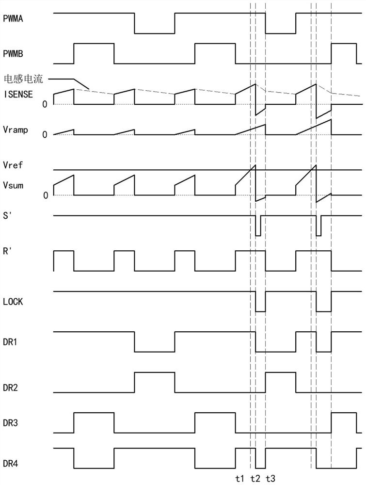
[0106] In Embodiment 1, the current sampling point is located in the DC input loop, that is, the current sensor collects the DC input current of the H-bridge, and the sensor will introduce parasitic inductance, which has an adverse effect on the switching transistor, and is not suitable for DC-AC conversion with a power greater than 10kW device, while this example gives Figure 5 The inductor current sampling method shown can be used for DC-AC converters exceeding 10kW. The difference between this embodiment and the first embodiment is that the sampling position of the current sensor 107 is different, and the current sensing signal ISENSE is generated after passing through the rectification circuit 122 . Figure 5 The medium current sensor 107 adopts a Hall sensor and is located between the inductor 110 and the first voltage node 103 . The output signal of the current sensor 107 passes through the rectification circuit 122 to generate a current sensing signal ISENSE. The work...


PUM


Abstract

The present invention relates to a current limiting system and a current limiting method used in a DC-AC converter, in particular to a DC-AC converter switching cycle-by-switching peak current limiting system and method, which solves the problem that traditional DC-AC converters are difficult to achieve peak current limiting The problem. The switching cycle-by-switching peak current limiting system of the present invention comprises a control drive circuit, a DC-AC conversion circuit and a current limiting control circuit. Among them, the current limiting control circuit is realized by analog circuit, including logic synthesis unit, slope compensation unit, summation unit, current limiting comparator, SR latch, NOT gate, adding slope compensation unit to eliminate the secondary caused by switching frequency Harmonic oscillation, fast response, stable working condition. At the same time, the present invention provides a method for limiting the peak current of the above-mentioned DC-AC converter by switching cycle. In addition, the present invention also proposes a system and method for limiting the peak current of a DC-AC converter switching cycle by switching cycle with a power greater than 10kW.

Description

technical field [0001] The invention relates to a current limiting system and a current limiting method used in a DC-AC converter, in particular to a DC-AC converter peak current limiting system and method by switching cycle. Background technique [0002] There are two traditional current limiting circuits: one is the current limiting technology based on average current control; the other is the current limiting technology based on peak current control. The performance of the current-limiting circuit using average current control depends largely on the response speed of the controller: the controller responds quickly, which may easily cause insufficient system loop margin and oscillate; Overshoot, resulting in the overshoot of the current limit point several times, can not achieve the ideal purpose of current limit protection. However, the response speed of the peak current limiting mode is fast, and the delay time can be as small as tens of nanoseconds to hundreds of nanos...

Claims


Application Information

Patent Timeline
Patent Type & Authority Patents(China)
IPC IPC(8): H02M1/088H02M7/5387H02M1/32
CPCH02M1/088H02M1/32H02M7/53871
Inventor 常军
Owner XIAN ACTIONPOWER ELECTRIC
Why Eureka
Try Eureka