
Temperature control system of hydraulic retarder

A temperature control system, hydraulic retarder technology, applied in the direction of liquid resistance brakes, magnetic drive clutches, clutches, etc., can solve the asymmetry of heat dissipation capacity, can not bypass the temperature control, and the heat dissipation capacity of the water tank can not solve the hydraulic retardation To solve problems such as heat of the controller, achieve the effect of smooth torque output curve, reduce excessive attention, and shorten training time

Pending Publication Date: 2020-08-25
十堰市恒能节能环保科技有限公司
View PDF0 Cites 0 Cited by
  • Summary
  • Abstract
  • Description
  • Claims
  • Application Information

AI Technical Summary

Problems solved by technology

[0004] 3. Looking at the entire system, the heat dissipation capacity of the engine cooling system has an upper limit, but the vehicle's load, speed, and potential energy brought by the slope are not easy to determine the upper limit. The speed at which heat energy is generated in this system Asymmetry with heat dissipation capacity per unit time
[0005] 4. All hydraulic retarder products have unavoidable temperature control problems that need to be solved
[0007] 6. Due to the relationship between the cooling system of the existing hydraulic retarder and the engine speed, we think it is necessary to explain the change of the driver's driving behavior: When the hydraulic retarder is activated, the vehicle is generally in the lower position. In the stage of slope or idling with gears, the engine speed is usually only about 1000 rpm or even lower, and the heat dissipation capacity of the water tank cannot solve the heat generated by the hydraulic retarder.

Method used


Image

  • Temperature control system of hydraulic retarder
  • Temperature control system of hydraulic retarder
  • Temperature control system of hydraulic retarder

Examples


Embodiment Construction

[0019] The following will clearly and completely describe the technical solutions in the embodiments of the present invention with reference to the accompanying drawings in the embodiments of the present invention. Obviously, the described embodiments are only some of the embodiments of the present invention, not all of them.

[0020] Since the heat dissipation system of the hydraulic retarder must be connected in series with the engine heat dissipation system, the problems are as follows: 1. The engine speed is required to be no less than 1800 rpm under working conditions; the working temperature must not reach or exceed 160 degrees Celsius, which distracts the driver's attention force.

[0021] 2. Due to the working conditions of the engine and the nature of heat exchange between oil and water, it runs at high temperature for a long time and its parameters and performance boundaries, resulting in insufficient torque and damage to the body.

[0022] 3. The pipelines of the en...


PUM


Abstract

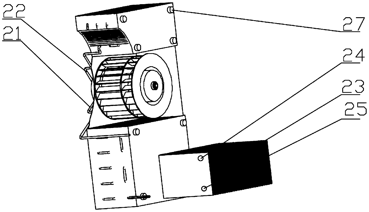
The invention discloses a temperature control system of a hydraulic retarder. An internal thread is designed at an axis portion of the tail end of a main shaft of a rotor of the retarder, so that themain shaft is connected with an external thread bush. The other end of the bush is connected with a round iron piece through a pipe thread. A temperature sensor is then designed to actually measure anoil temperature of an oil storage cavity, when a working condition temperature exceeds a set temperature, an electromagnetic coil is started to drive a slider, the slider is driven by the electromagnetic coil to be tightly adsorbed to the round iron piece, and torque transmission is completed. The torque is used for driving a scroll compressor to compress a refrigerant to act. A compressor main shaft is equipped with a group of axial fans for cooling condensers. A cooler is arranged in the oil storage cavity and directly regulates a temperature of medium oil. When the oil temperature is suitable for working conditions, the electromagnetic coil is powered off, at the moment, the slider stops adsorbing the round iron piece, torque disconnection is realized, and the compressor is stopped instantly. In this way, temperature self-control is realized.

Description

technical field [0001] The invention relates to the technical field of automobile manufacturing, in particular to a temperature control system of a hydraulic retarder. Background technique [0002] 1. Heavy-duty vehicles have idling brakes, exhaust brakes and wheel hub brakes. As far as the working conditions are concerned, their capabilities still cannot meet the requirements of use. The braking power of the first two is weak, which will damage the main engine. Those who use it frequently will get hot and have accidents. Over the years, most social vehicles have been equipped with water showers to cool down the brake hubs, but this will affect the safety of other vehicles during use. For itself, the alternation of cold and heat will also cause material cracks and cause accidents. With the advancement of the GB7258-2017 standard, in the past two years, the hydraulic retarder has been installed as an optional part in a small number of vehicles in the main engine factory, and...

Claims


Application Information

Patent Timeline
IPC IPC(8): F16D57/02F16H57/04F16D27/14
CPCF16D27/14F16D57/02F16H57/0416F16H57/0417
Inventor 林承义
Owner 十堰市恒能节能环保科技有限公司
Learn More