Ductile cast iron spiral pile

A ductile iron and screw pile technology, applied in the field of screw piles, can solve the problems of irregular shape of the rotor, difficult transportation, large space occupation, etc., and achieve the effects of reducing transportation costs, improving transportation efficiency, and avoiding cracking.

Inactive Publication Date: 2020-08-25
大连利旋电力工程技术有限公司
View PDF6 Cites 0 Cited by
  • Summary
  • Abstract
  • Description
  • Claims
  • Application Information

AI Technical Summary

Problems solved by technology

The disadvantages of the ductile iron screw pile are: due to the irregular shape of the rotor, the ductile iron screw pile takes up a lot of space for loading and is difficult to transport

Method used


Image

  • Ductile cast iron spiral pile
  • Ductile cast iron spiral pile
  • Ductile cast iron spiral pile

Examples


Embodiment 1

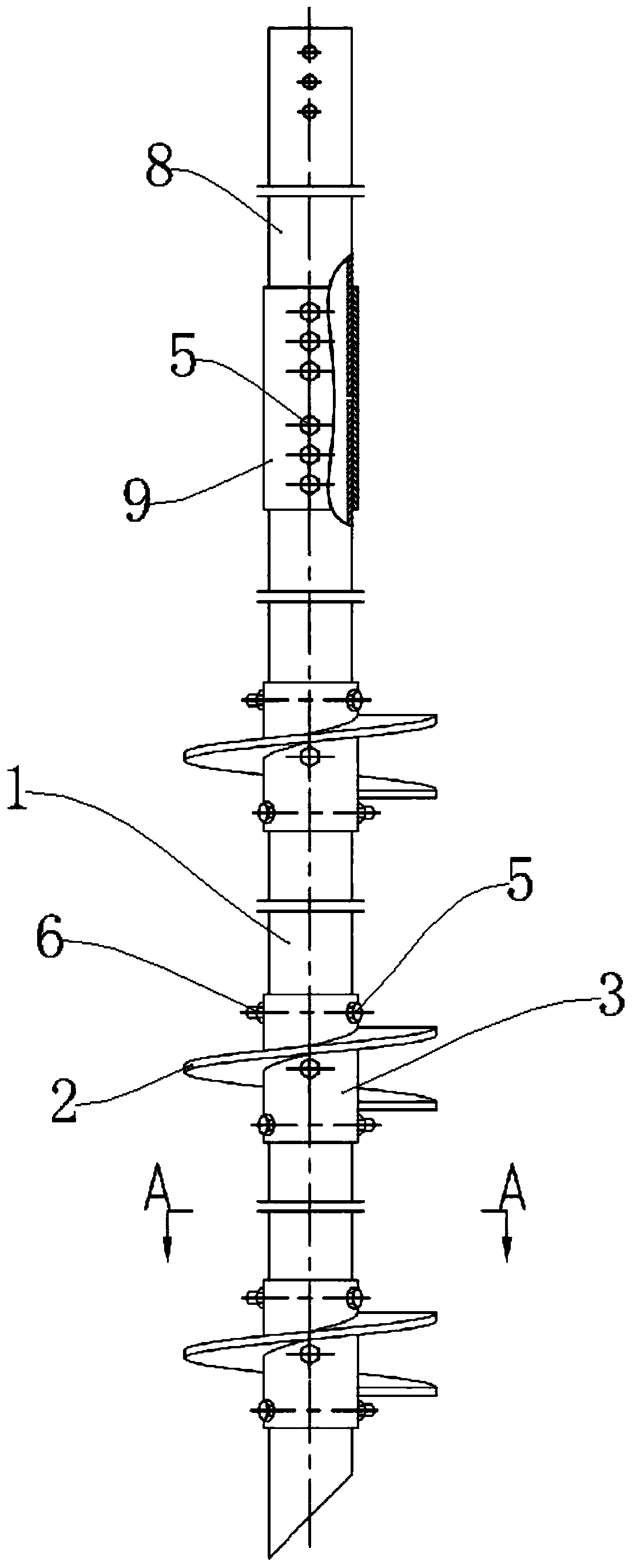
[0029] Such as Figure 1-Figure 5 As shown, a nodular cast iron screw pile includes a guide tube 1, a rotor 2, a rotor sleeve 3, an extension tube 8 and a connecting sleeve. Both the guide pipe 1 and the extension pipe 8 are made of ductile iron, and the rotor 2, the rotor sleeve 3 and the connecting sleeve are made of Q345 steel.

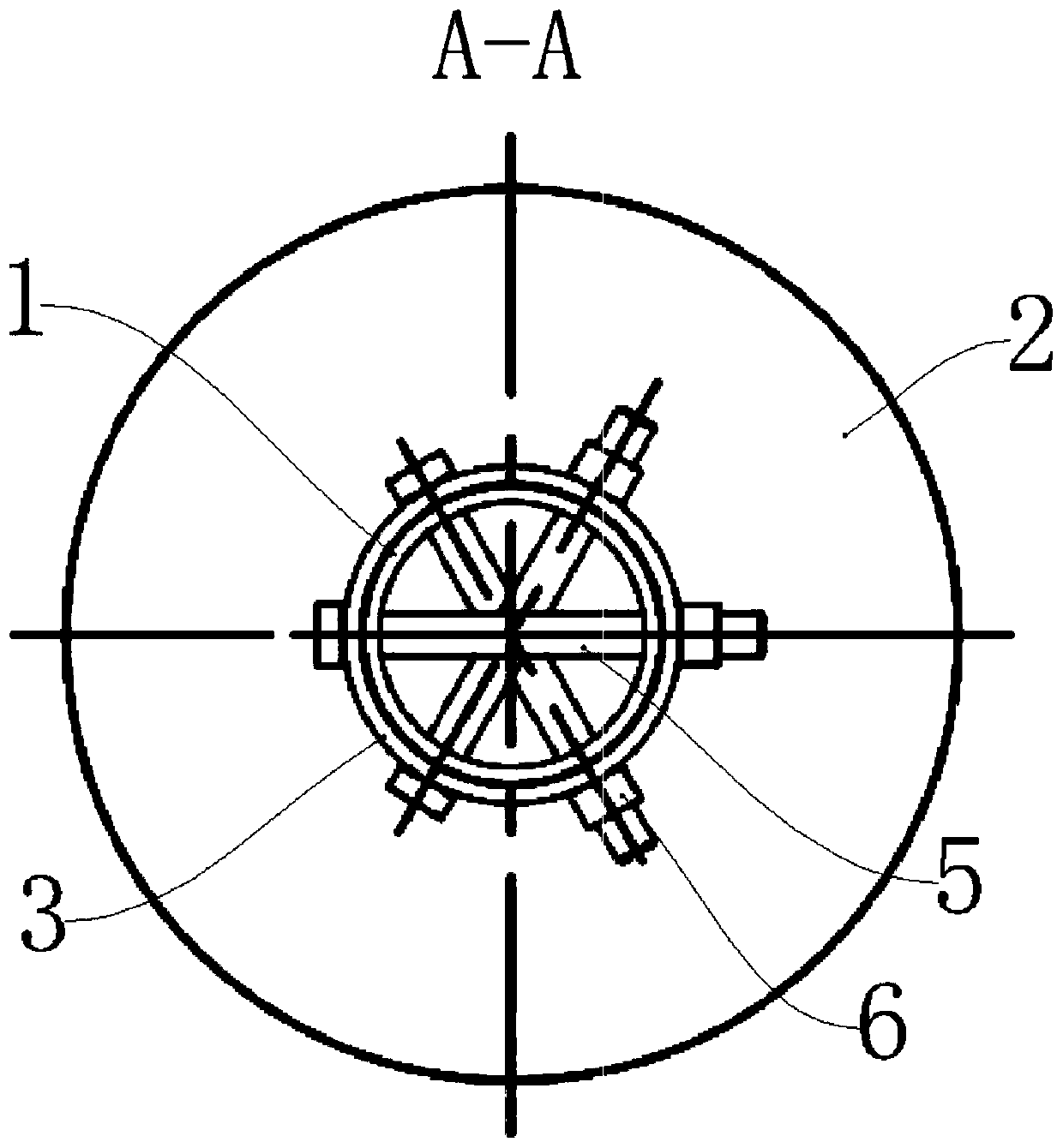
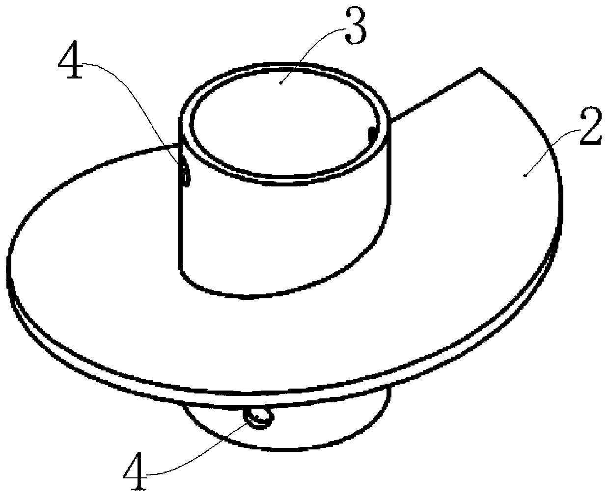
[0030] The rotor 2 is in a spiral shape, and the rotor 2 is welded to the rotor sleeve 3 , and each rotor sleeve 3 is provided with a rotor 2 . The rotor sleeve 3 is socketed with the guide pipe 1 and fixedly connected through a threaded connector, specifically, as Figure 3-Figure 5 As shown, the rotor sleeve 3 and the guide tube 1 are respectively provided with three connecting holes 4 matching the threaded connectors. The axis of the connecting holes 4 is horizontal and intersects the axis of the guide tube 1. Any two connecting holes The axes of 4 are not coplanar. In the first embodiment, the rotor sleeve 3 is fixedly connected with the gui...

Embodiment 2

[0045] Such as Figure 6 As shown, a nodular cast iron screw pile includes a guide tube 1, a rotor 2, a rotor sleeve 3, an extension tube 8 and a connecting sleeve. The guide tube 1, rotor 2, rotor sleeve 3, extension tube 8 and connecting sleeve are all made of ductile iron, so the manufacturing cost of the screw pile in this embodiment is relatively low.

[0046] The rotor 2 is helical, and the rotor 2 and the rotor sleeve 3 are integrally cast. Each rotor sleeve 3 is provided with a rotor 2 . The rotor sleeve 3 is socketed with the guide pipe 1 and fixedly connected through a threaded connector, specifically, as Figure 6 As shown, the rotor sleeve 3 and the guide tube 1 are respectively provided with three connecting holes 4 matching the threaded connectors. The axis of the connecting holes 4 is horizontal and intersects the axis of the guide tube 1. Any two connecting holes The axes of 4 are not coplanar. In the second embodiment, the rotor casing 3 and the guide pipe...


PUM

PropertyMeasurementUnit
lengthaaaaaaaaaa
thicknessaaaaaaaaaa
thicknessaaaaaaaaaa

Abstract

The invention relates to the field of spiral piles, in particular to a ductile cast iron spiral pile. The ductile cast iron spiral pile comprises a guide pipe, a rotor wing and a rotor wing sleeve, the guide pipe is made of ductile cast iron, the rotor wing is spirally shaped, the rotor wing and the rotor wing sleeve are fixedly connected, and the rotor wing sleeve and the guide pipe are connectedin a sleeving mode and are fixedly connected through a threaded connecting piece. Compared with the prior art, the ductile cast iron spiral pile has the beneficial effects that the rotor wing is fixedly installed on the guide pipe through the threaded connecting piece, so that separate carrying and rapid field assembly of the rotor wing and the guide pipe are achieved, the space of a transportation is fully used, the transportation cost is reduced, the efficiency of transportation is improved, the high corrosion resistance of ductile cast iron is fully used, and the cracking problem of the ductile cast iron due to welding is avoided.

Description

technical field [0001] The invention relates to the field of screw piles, in particular to a nodular cast iron screw pile. Background technique [0002] At present, there are many types of foundation piles commonly used in the engineering field, such as cement pouring piles, steel screw piles, steel hammer piles and ductile iron hammer piles. [0003] The construction process of cement pouring piles is complicated. The lower steel pipe is drilled and cement is injected to seal it. Not only the construction period is long, but also it is not environmentally friendly. [0004] Both steel screw piles and steel hammer piles are made of steel, which has the advantages of high material strength and easy welding; the disadvantage is that the corrosion resistance is poor, and the application range is affected. If the surface of the product is galvanized and anti-corrosion, it will cause damage to the environment and increase Cost of production. [0005] Ductile iron hammer piles a...

Claims


Application Information

Patent Timeline
Patent Type & Authority Applications(China)
IPC IPC(8): E02D5/56E02D5/28
CPCE02D5/285E02D5/56
Inventor 于逸飞
Owner 大连利旋电力工程技术有限公司
Why Eureka
Try Eureka