


Quick Research
Generate reliable direction feasibility study reports for your R&D in just a few steps.

Technical Q&A
Discover and master advanced knowledge NOW. Basics, ideas, possibilities, all at once.

Find Solutions
As an expert in R&D theories, this can generate solutions to your technical problems instantly.

Evaluate Feasibility
Analyze your overall solution with one click, know your potential R&D risks in advance.

Monitor Landscape
Get weekly tech updates, stay abreast of the latest tech innovations and key insights.
Rotary impact type ultrasonic rock grinding device driven by single energy flow
A single-energy, impact-type technology, applied in the field of deep space exploration, can solve the problems of difficult removal of grinding debris and the impact of grinding debris on grinding efficiency, and achieve the effects of improved rock grinding efficiency, simplified structure, and reduced volume
- Summary
- Abstract
- Description
- Claims
- Application Information
AI Technical Summary
Problems solved by technology
Method used
Image

Examples
specific Embodiment approach 1
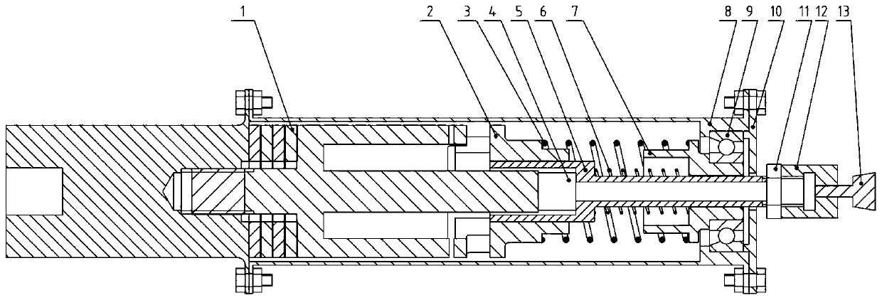
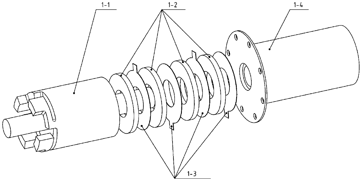
[0022] Specific implementation mode one: combine Figure 1 to Figure 2 Describe this embodiment, a rotary impact type ultrasonic rock grinding device driven by a single energy flow in this embodiment includes a grinding shell assembly, which also includes a longitudinal-torsional composite piezoelectric transducer 1, a rotor 2, a pre- Tight spring 3, free mass block 4, grinding rod 5, recovery spring 6, copper sleeve 7, grinding head connector 12 and grinding head 13, longitudinal-torsional composite piezoelectric transducer 1 is horizontally arranged and connected with the horizontally arranged The front end of the grinding shell assembly is connected, the copper sleeve 7 is installed at the inner rear end of the grinding shell assembly, the grinding rod 5 is horizontally installed in the grinding shell assembly, and the rear end of the grinding rod 5 protrudes from the grinding The shell assembly is connected with the grinding head connector 12, the grinding head 13 is insta...
specific Embodiment approach 2
[0026] Specific implementation mode two: combination figure 1 This embodiment will be described. The longitudinal-torsional composite piezoelectric transducer 1 of this embodiment is connected to the front end of the grinding shell assembly through a flange. With such arrangement, the connection method is simple, easy to disassemble and assemble, and the connection is reliable. Other compositions and connections are the same as in the first embodiment.
specific Embodiment approach 3
[0027] Specific implementation mode three: combination figure 1 This embodiment is described. The grinding shell assembly of this embodiment includes a shell 8, a slewing bearing 9 and an end cover 10. The slewing bearing 9 is set between the inner wall of the shell 8 and the outer wall of the copper sleeve 7. The shell The rear end of 8 is detachably connected with end cover 10. Such arrangement has a simple structure and is convenient for manufacture. Other compositions and connections are the same as those in Embodiment 1 or Embodiment 2.
PUM
 Abstract
Description
Claims
Application Information
 - R&D Engineer
- R&D Manager
- IP Professional
- Industry Leading Data Capabilities
- Powerful AI technology
- Patent DNA Extraction
Browse by: Latest US Patents, China's latest patents, Technical Efficacy Thesaurus, Application Domain, Technology Topic, Popular Technical Reports.
© 2024 PatSnap. All rights reserved.Legal|Privacy policy|Modern Slavery Act Transparency Statement|Sitemap|About US| Contact US: help@patsnap.com