3D laser cutting device

A cutting device and three-dimensional laser technology, which are applied in laser welding equipment, devices for coating liquid on surfaces, and manufacturing tools, etc., can solve the problems of small pipe fittings containing waste and the inability to realize automatic separation of workpiece and waste.

Active Publication Date: 2021-09-14
WENZHOU UNIVERSITY
View PDF10 Cites 0 Cited by
  • Summary
  • Abstract
  • Description
  • Claims
  • Application Information

AI Technical Summary

Problems solved by technology

[0004] The present invention intends to provide a three-dimensional laser cutting device to solve the problem that in the prior art, when the laser cutting device processes a long tube workpiece into a plurality of small tubes with multiple processing surfaces, the processed small tubes contain waste materials. But the problem of automatic separation of workpiece and waste cannot be realized

Method used


Image

  • 3D laser cutting device
  • 3D laser cutting device
  • 3D laser cutting device

Examples


Embodiment 1

[0036] Embodiment one is basically as attached Figure 1 to Figure 4 Shown:

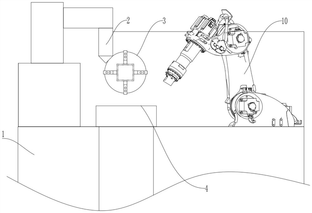
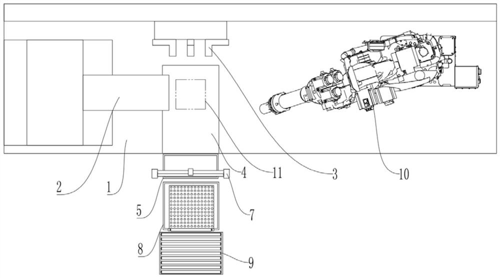
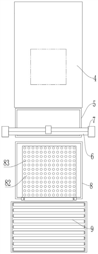
[0037] combine Figure 1 to Figure 3 , a three-dimensional laser cutting device, including a workbench 1, a laser cutter 2, a fixture 3, a receiving conveyor line 4, a collection box 5, a support rod 6, a toggle assembly 7, an oil tank 8, and a discharging conveyor line 9, and the receiving conveyor The line 4 adopts a belt-driven conveying line, and the laser cutter 2 and the fixture 3 are both installed on the workbench 1, and the manipulator 10 for transferring the workpiece to be processed to the fixture 3 is also installed on the workbench 1.

[0038] The upper surface of the receiving conveying line 4 is provided with refractory materials, the receiving conveying line 4 is located on the workbench 1 , and the receiving conveying line 4 is located below the laser cutter 2 .

[0039] combine Figure 4 , according to the transmission direction of the workpiece from left to right (the present em...

Embodiment 2

[0052] Embodiment two is basically as attached Figure 5 As shown, embodiment two has carried out following improvement on the basis of embodiment one:

[0053] The receiving conveying line 4 includes an annular conveyor belt 41, the surface of which is pasted with refractory material, and the upper surface of the conveyor belt 41 is covered with an annular metal mesh 42, and an elastic member is installed between the metal mesh 42 and the conveyor belt 41, and the elastic member Spring 43 is adopted; dust removal brush 44 is installed on the bottom of material receiving conveying line 4, and dust removal brush 44 is used for brushing off the sundries on metal mesh 42 and conveyer belt 41.

[0054] When adopting this embodiment, the small square tube 11 cut off by the laser cutter 2 directly falls onto the metal mesh 42, and the spring 43 makes the metal mesh 42 have better cushioning performance, which can reduce the impact caused by the falling of the small square tube 11. ...


PUM


Abstract

The invention relates to the technical field of laser cutting, and specifically discloses a three-dimensional laser cutting device, including a workbench, a laser cutter, and a fixture, and also includes a material receiving conveyor line, a support rod, a toggle assembly, and a material discharging conveyor line. The material receiving conveyor line is located at On the workbench, the feeding conveying line is located under the laser cutter; the supporting rod is located between the discharging conveying line and the receiving conveying line, the distance between the supporting rod and the end of the conveying line is greater than half of the length of the workpiece, and the supporting rod is lower than The material receiving conveying line; the driving assembly includes a rotatable driving lever, which is located above the support rod, and the driving rod is used to move the workpiece between the material receiving conveying line and the supporting rod to the discharging conveying line. This solution is used to solve the problem that in the prior art, when the laser cutting device processes long tube workpieces into multiple small tubes with multiple processing surfaces, the processed small tubes contain waste materials and cannot realize the automatic processing of workpieces and waste materials. The problem of separation.

Description

technical field [0001] The invention relates to the technical field of laser cutting, in particular to a three-dimensional laser cutting device. Background technique [0002] Three-dimensional laser cutting technology uses a high-power-density laser beam to scan the surface of the material, and heats the material to thousands to tens of thousands of degrees Celsius in a very short period of time to melt or gasify the material, and then uses high-pressure gas to melt or vaporize the material from the cut Blow away in the seam to achieve the purpose of cutting materials. [0003] When laser cutting is used, the manipulator can be used as a fixture to hold the piece to be cut, or as a device to transfer the piece to be cut. After the manipulator picks up the piece to be cut, it puts the piece to be cut on the fixture. Furniture realizes the clamping action; for cutting long tubes to be processed into multiple small tubes, and cutting on multiple surfaces of each small tube, su...

Claims


Application Information

Patent Timeline
Patent Type & Authority Patents(China)
IPC IPC(8): B23K26/38B23K26/70B23K26/16B05C3/10B05C13/02B23K101/06
CPCB05C3/10B05C13/02B23K26/16B23K26/38B23K26/702B23K2101/06
Inventor 林礼区
Owner WENZHOU UNIVERSITY
Why Eureka
Try Eureka