Continuous casting machine casting device and casting method

A pouring method and technology of a continuous casting machine, applied in the field of metallurgy, can solve the problems of short ladle pouring time, lowering liquid level, affecting the continuous stability and uniformity of continuous casting billet quality, etc. The temperature of molten steel is sufficiently uniform and the effect of continuous undifferentiated solidification and forming is realized

Active Publication Date: 2020-08-25
CONTINUOUS CASTING TECH ENG OF CHINA
View PDF7 Cites 0 Cited by
  • Summary
  • Abstract
  • Description
  • Claims
  • Application Information

AI Technical Summary

Problems solved by technology

Therefore, during the intermittent period when the ladle turret turns and switches ladles, no molten steel is added to the tundish, but the flux of molten steel from the tundish to the crystallizer does not change, resulting in a decrease in the liquid level of the molten steel in the tundish, and the molten steel in the tundish When the temperature and flow field change, the floating behavior of the molten steel in the tundish also changes, which also has an adverse effect on the purity of the molten steel. , the temperature of molten steel in the tundish, the flow field, and the floating behavior of inclusions will change again, resulting in poor quality stability of the continuous casting slab during this period
Especially with the rapid development of continuous casting high-efficiency technology and the development of endless continuous casting and rolling process technology, the casting speed of continuous casting machine is getting higher and higher. The furnace capacity has not been increased, resulting in shorter and shorter ladle pouring time and more frequent replacement of ladle pouring, which seriously affects the continuous stability and uniformity of continuous casting slab quality

Method used


Image

  • Continuous casting machine casting device and casting method
  • Continuous casting machine casting device and casting method
  • Continuous casting machine casting device and casting method

Examples


Embodiment Construction

[0030] Embodiments of the pouring device and pouring method of the continuous casting machine according to the present invention will be described below with reference to the accompanying drawings. Those skilled in the art would recognize that the described embodiments can be modified in various ways or combinations thereof without departing from the spirit and scope of the invention. Accordingly, the drawings and description are illustrative in nature and not intended to limit the scope of the claims. Also, in this specification, the drawings are not drawn to scale, and like reference numerals denote like parts.

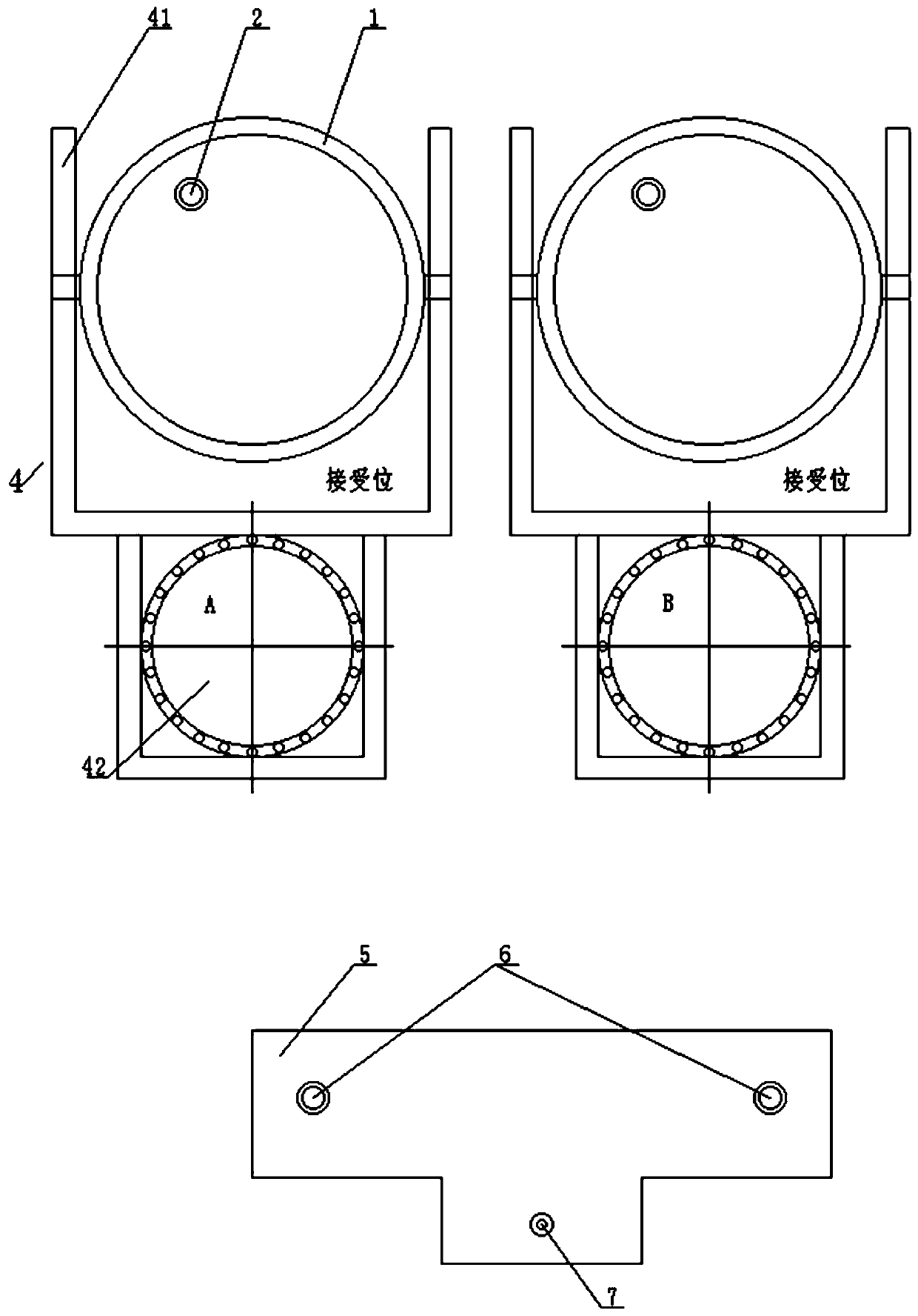
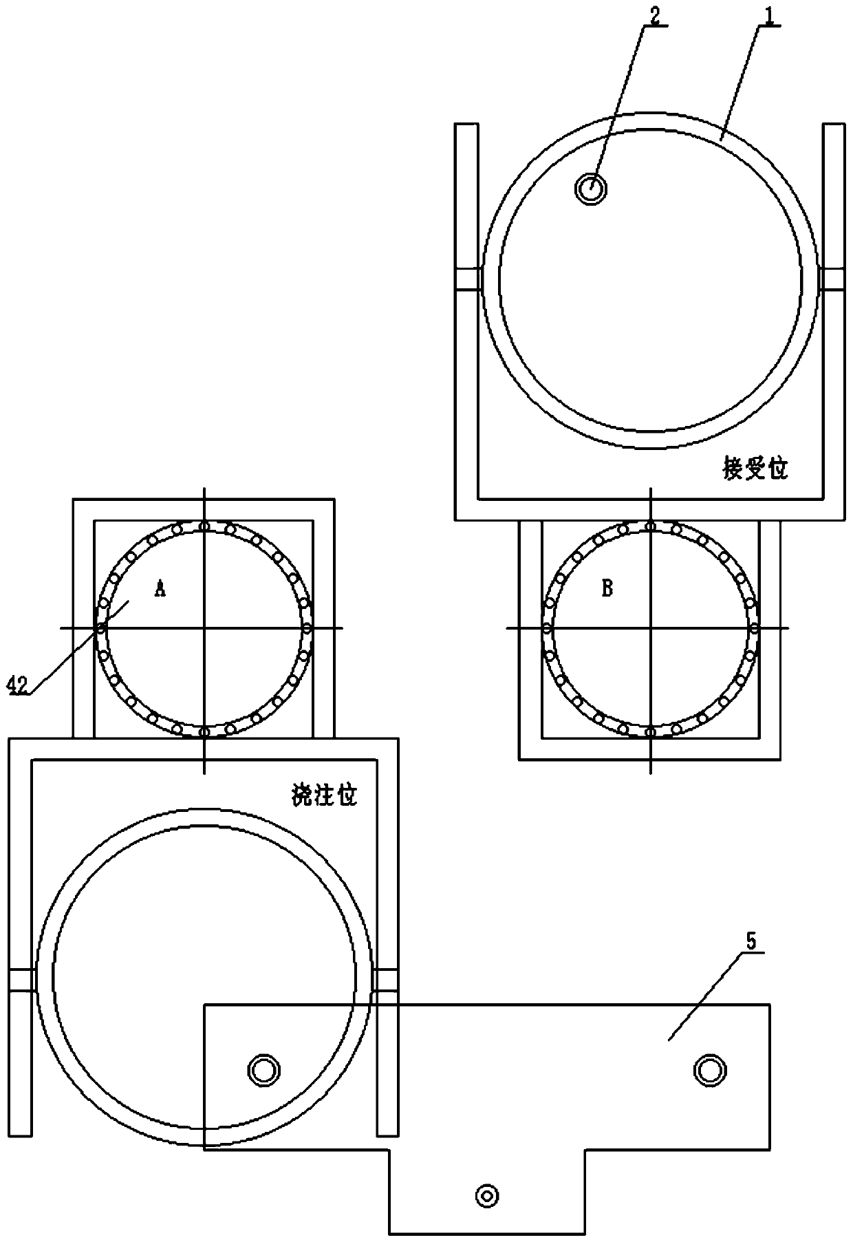
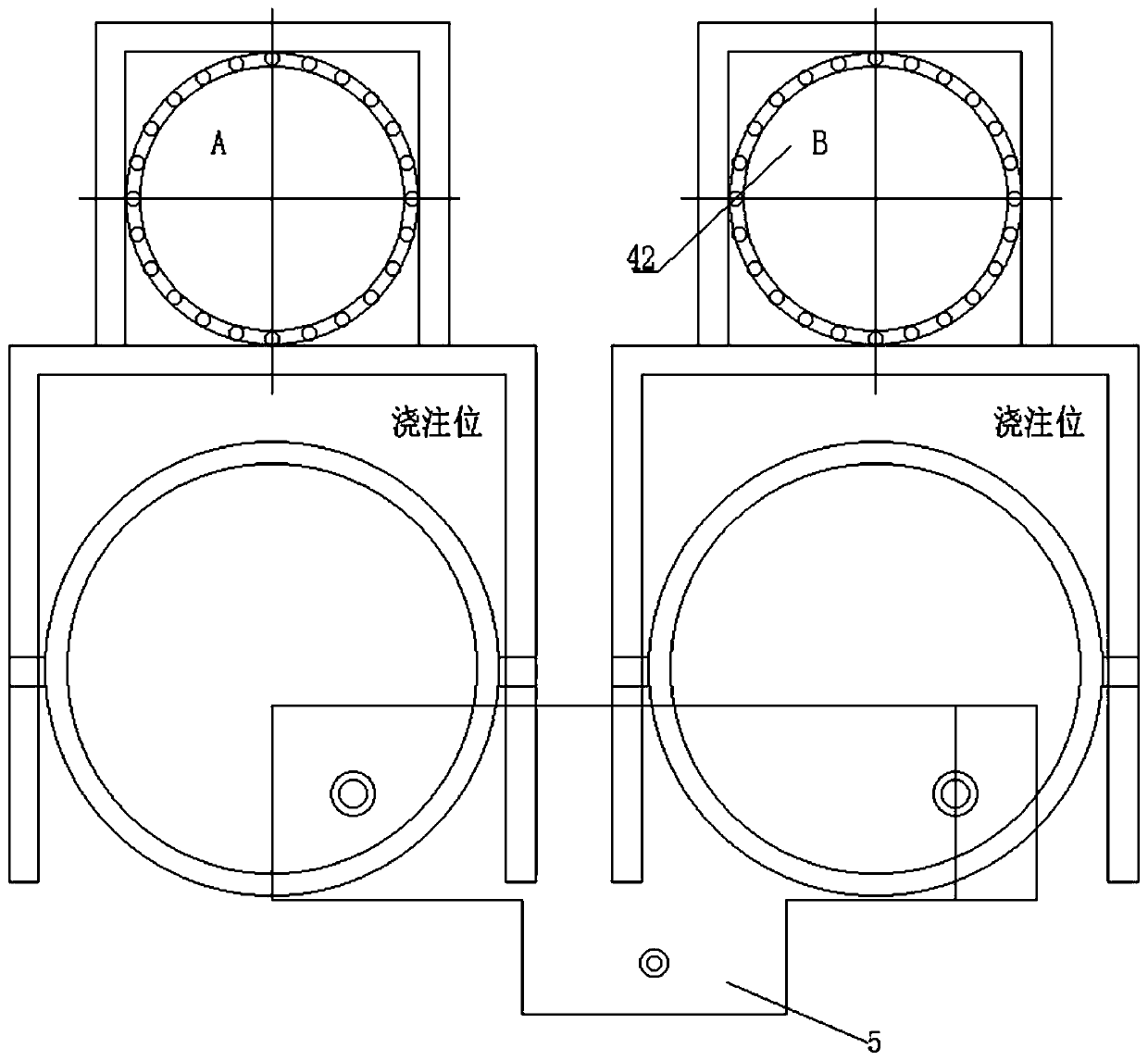
[0031] The pouring device of the continuous casting machine in this embodiment includes a double ladle turret, a tundish 5 , a crystallizer 9 , a slab support system 10 , a cooling system 11 , and a casting system 12 . Wherein, the double-ladle turret includes two single-arm turrets 4 arranged side by side, and any one-arm turret 4 can rotate around the slewing sup...


PUM


Abstract

The invention discloses a continuous casting machine casting device and casting method. The device comprises a dual ladle turret and an intermediate tank, wherein the dual ladle turret comprises two single-arm revolving platforms; any single-arm revolving platform can rotate around a revolving support to a steel ladle receiving position in order to receive a steel ladle, and rotate to a molten steel casting position for pouring molten steel in the steel ladle to the intermediate tank; injection holes which are in butt joint with a sliding gate nozzle of the steel ladle are formed in the upperend of the intermediate tank; a water gap for pouring the molten steel into a crystallizer is formed in the lower end of the intermediate tank; the two single-arm revolving platforms revolve to the molten steel pouring position after receiving the steel ladle from the steel ladle receiving position in order to pour the molten steel into the crystallizer; and the molten steel poured into the intermediate tank is the same as the molten steel flowing from the intermediate tank to the crystallizer in flux through adjustment of the aperture of the sliding gate nozzle, so that the liquid level of the intermediate tank is kept stable, and the molten steel components and molten steel temperatures of different heat numbers are uniform. Through adoption of the continuous casting machine casting device, the molten steel jointing time difference generated by replacement of the steel ladle is eliminated; stable liquid level, temperature field, flow field, inclusion removing behavior and molten steel components of the molten steel are ensured; and continuous and nondifferential solidification and deformation of the molten steel are realized.

Description

technical field [0001] The invention relates to the technical field of metallurgy, in particular to a pouring device and a pouring method for a continuous casting machine. Background technique [0002] Continuous casting is an important link in the current steel production process. Qualified molten steel is continuously and stably solidified through the continuous casting process to provide qualified billets for subsequent rolling. [0003] Since the qualified molten steel smelted in the steelmaking process is stored and transported through ladles with a certain capacity, in order to avoid interruption of continuous casting and pouring due to inversion of the ladle, the continuous casting machine is equipped with equipment such as a ladle turret and a tundish for transferring molten steel. The qualified molten steel smelted in the steelmaking process is hoisted to the receiving position of the ladle turret and waits for pouring. The molten steel at the pouring position of th...

Claims


Application Information

Patent Timeline
Patent Type & Authority Applications(China)
IPC IPC(8): B22D11/14B22D11/18B22D41/13B22D41/24B22D41/50
CPCB22D11/142B22D11/18B22D41/13B22D41/24B22D41/50
Inventor 韩占光周干水谢长川李智潘国友
Owner CONTINUOUS CASTING TECH ENG OF CHINA
Why Eureka
Try Eureka