
Macromolecule UV decoration plate cleaning equipment and work method thereof

A technology for cleaning equipment and decorative boards, applied in cleaning methods and utensils, cleaning methods using liquids, cleaning methods using gas flow, etc., can solve the problems of low board loading efficiency and inconvenient loading, and achieve board loading efficiency high effect

Active Publication Date: 2020-08-25
李壮
View PDF8 Cites 3 Cited by
  • Summary
  • Abstract
  • Description
  • Claims
  • Application Information

AI Technical Summary

Problems solved by technology

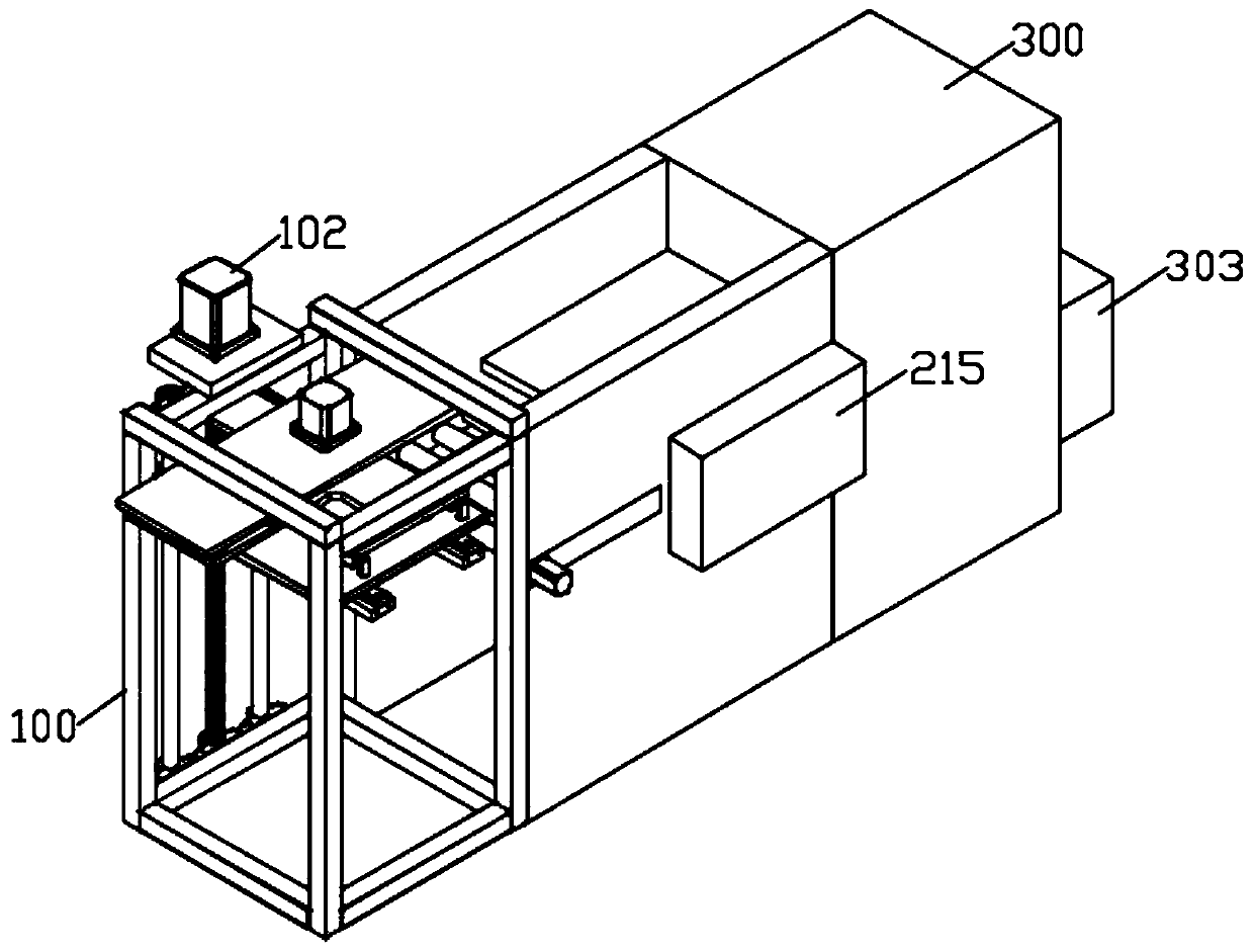
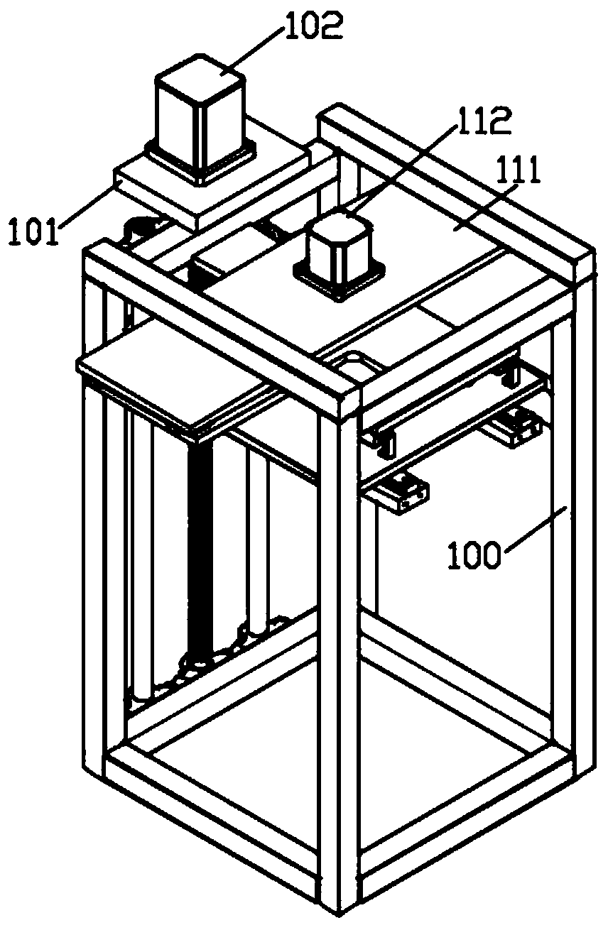
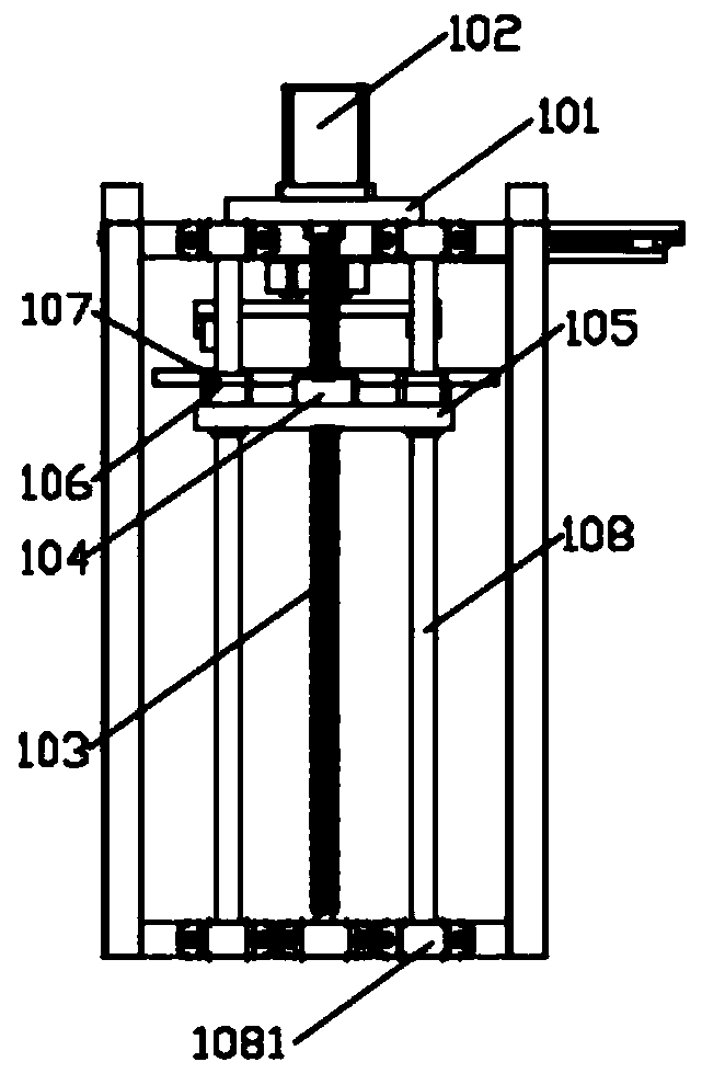
[0004] The object of the present invention is to provide a kind of polymer UV decorative plate cleaning equipment and its working method, solve the following technical problems: (1) drive the screw rod to rotate through the output shaft of the first motor, and the screw rod cooperates with the screw rod connecting block to drive the movable plate to descend , the movable plate drives the rod sleeve to slide down along the positioning rod, and then drives the feeding plate down to the bottom of the feeding frame through the first slide rail, and pulls the feeding plate outward, and the feeding plate passes through the first slider along the direction of the first slide rail Slide out the upper material rack, then stack the polymer UV decorative boards on the upper material board, push the upper material board, push the upper material board back into the upper material rack, the first motor drives the upper material board to rise, and then the first The piston rod of the cylinder pushes the connecting plate down, and the connecting plate drives the clamping block down through the second cylinder, and the clamping block drops to the side of the top polymer UV decorative plate, and the piston rod of the second cylinder shrinks, and the top polymer UV decorative plate The plate is clamped, and then the output shaft of the second motor drives the gear to rotate, and the gear cooperates with the rack to drive the moving plate to move out of the feeding rack, and then the polymer UV decorative board is moved out of the feeding rack and placed on the conveyor roller on the cleaning rack to solve the problem. There are technical problems such as inconvenient loading of polymer UV decorative panels at high positions and low loading efficiency; (2) The output shaft of the third motor drives one of the first drive rods to rotate, and the four first drive rods cooperate with the first pulley The belt drives the four conveying rollers to rotate, and the conveying rollers convey the polymer UV decorative plate to the two installation frames. The piston rod of the third cylinder drives the lifting shell up and down, and then drives the sticky dust roller on the installation frame to rise and fall. The two installation The sticky rollers on the frame contact the polymer UV decorative plate and the lower surface respectively, the output shaft of the fourth motor drives one of the second drive rods to rotate, and the four second drive rods cooperate with the second pulley and the belt to drive the four sticky rollers Rotate, the sticky dust roller transports the polymer UV decorative board and removes the dust on its surface at the same time, the air blower in the lifting shell blows soot on the surface of the polymer UV decorative board, and the negative pressure fan blows the dust through the dust collection net and The port is extracted into the dust collection case, which solves the technical problem that the surface cleaning equipment in the prior art cannot transport the polymer UV decorative board while cleaning, and solves the technical problem that the dust on the surface of the polymer UV decorative board is not easy to collect and remove in the prior art; (3) The polymer UV decorative boards are put in sequentially from the plate inlet, the polymer UV decorative boards enter between the upper slant plate and the lower slant plate, the water in the first water tank is drawn by the water pump and passed through the first nozzle to spray the polymer UV The upper surface of the decorative plate is sprayed, the water in the second water tank is drawn by the water pump and sprayed on the lower surface of the polymer UV decorative plate through the second nozzle, the polymer UV decorative plate is guided to slide to the blanking plate, the fifth cylinder piston The rod pushes down the lifting plate, and the lifting plate drives the blanking plate down through the connecting plate, the polymer UV decorative plate is stacked on the blanking plate, the hot air blower dries the polymer UV decorative plate on the blanking plate, and the blanking plate is stuck into the rectangular groove on the baffle, and then the piston rod of the fourth cylinder pushes the thrust plate, and the thrust plate pushes the bottom polymer UV decorative plate out from the plate outlet, which is convenient for the polymer UV decorative plate to be transported during the cleaning process. Simultaneously dry multiple polymer UV decorative panels, and at the same time facilitate the removal of polymer UV decorative panels

Method used


Image

  • Macromolecule UV decoration plate cleaning equipment and work method thereof
  • Macromolecule UV decoration plate cleaning equipment and work method thereof
  • Macromolecule UV decoration plate cleaning equipment and work method thereof

Examples


Embodiment Construction

[0043] The following will clearly and completely describe the technical solutions in the embodiments of the present invention with reference to the accompanying drawings in the embodiments of the present invention. Obviously, the described embodiments are only some, not all, embodiments of the present invention. Based on the embodiments of the present invention, all other embodiments obtained by persons of ordinary skill in the art without creative efforts fall within the protection scope of the present invention.

[0044] see Figure 1-17 As shown, the present invention is a kind of macromolecule UV decorative board cleaning equipment, comprises feeding rack 100, drying box 300, is provided with cleaning rack 200 between feeding rack 100 and drying box 300, and is installed on feeding rack 100 There is a motor plate 101, the first motor 102 is installed on the motor plate 101, the output shaft of the first motor 102 runs through the motor plate 101 and is connected with a scr...


PUM


Abstract

The invention discloses macromolecule UV decoration plate cleaning equipment and a work method thereof. A loading plate is pushed, and is pushed back into a loading frame, a first motor drives the loading plate to rise, a firs air cylinder push rod pushes a linking plate to descend, the linking plate drives a clamping block to descend through a second air cylinder, the clamping block descends to the position beside a macromolecule UV decoration plate on the topmost portion, a second air cylinder piston rod shrinks, the macromolecule UV decoration plate on the topmost part is clamped, a secondmotor output shaft drives a gear to rotate, the gear is matched with a rack to drive a moving plate to move out of the loading frame, the macromolecule UV decoration plate is moved out of the loadingframe and put on a conveying roller on a cleaning frame, and the technical problems that in the prior art, the macromolecule UV decoration plate is high in position and inconvenient to load, and loading efficiency is not high can be solved.

Description

technical field [0001] The invention relates to the technical field of polymer UV decorative panels, in particular to a polymer UV decorative panel cleaning device and a working method thereof. Background technique [0002] Polymer UV decorative panels are not easy to oxidize, fade, scratch and wear, especially in outdoor high temperature conditions, and have the function of high temperature resistance. Compared with ordinary polymer UV decorative panels, it can ensure the three-dimensional aesthetics of the decorative panels in high temperature environments. It is a decorative panel currently being promoted. [0003] The surface of the existing polymer UV decorative board needs to be cleaned before painting and polishing. When cleaning, the polymer UV decorative board needs to be sent into the cleaning equipment through the upper board device. The upper board at a high position is not convenient. The efficiency of the board is not high. During the cleaning process, the sur...

Claims


Application Information

Patent Timeline
IPC IPC(8): B08B7/00B08B13/00B08B15/04B08B5/02B08B3/02F26B9/06F26B21/00F26B25/00F26B25/02F26B25/18B65G47/82B65G47/90
CPCB08B7/0028B08B13/00B08B15/04B08B5/023B08B3/022F26B9/06F26B21/001F26B25/003F26B25/02F26B25/18B65G47/82B65G47/901
Inventor 李壮
Owner 李壮
Learn More