
Power supply adjusting system and power supply adjusting method

A regulation system and regulation method technology, which is applied in the direction of power network operating system integration, information technology support system, electrical components, etc. problems, to avoid delays in expansion, long supply time, and limited storage energy.

Pending Publication Date: 2020-08-21
深圳市聚能优电科技有限公司
View PDF2 Cites 2 Cited by
  • Summary
  • Abstract
  • Description
  • Claims
  • Application Information

AI Technical Summary

Problems solved by technology

[0006] It should be pointed out that when a diesel generator is applied to an emergency power supply occasion, the diesel generator itself will have serious defects: on the one hand, if the diesel generator is kept on and waiting for emergency power supply, the diesel generator will always generate fuel consumption and waste energy. Serious; on the other hand, if the diesel generator is always off and only starts to supply power to the load when the mains power supply is cut off, its startup process will generally take tens of seconds or even minutes, and the load will experience power supply during its startup process. gap
[0007] In addition to the above-mentioned situation of sudden interruption of mains power supply, power users generally face the problem of unbalanced supply and demand between mains power supply and power load. demand; or the load experiences low power consumption, and the mains supply is oversupplied; if the mains supply is insufficient, the power consumer needs the power supply department to apply for capacity expansion, and the application for temporary capacity of the mains is easy to be restricted, and the approval period is generally long. It is unrealistic for power consumers who are in urgent need of electricity

Method used


Image

  • Power supply adjusting system and power supply adjusting method

Examples


Embodiment Construction

[0045] In order to make the object, technical solution and advantages of the present invention clearer, the present invention will be further described in detail below in conjunction with the accompanying drawings and embodiments. It should be understood that the specific embodiments described here are only used to explain the present invention, not to limit the present invention.

[0046] To achieve the above object, the technical scheme of the present invention is as follows:

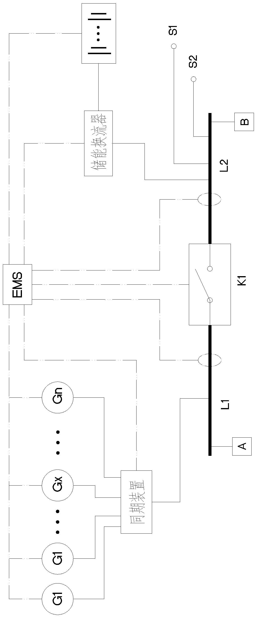
[0047] see figure 1 .

[0048] In this specific embodiment, a power supply regulation system is provided. The system includes a power supply side bus L1, a power consumption side bus L2, a switch K1, a fuel generator set, and an energy storage device. The external mains power is connected to the power supply side bus L1. The external load is connected to the power-side bus L2; ​​the switch is set between the power-side bus L1 and the power-side bus L2, one end of the switch is connected to the power...


PUM


Abstract

The invention discloses a power supply adjusting system which comprises a power supply side bus, a power utilization side bus, a change-over switch, a fuel generator set and an energy storage device,an external mains supply is connected to the power supply side bus, and an external load connected to the power utilization side bus. The change-over switch is arranged between the power supply side bus and the power utilization side bus, one end of the change-over switch is connected with the power supply side bus, the other end of the change-over switch is connected with the power utilization side bus, and the energy storage device is connected into the power utilization side bus. The invention further provides a power supply adjusting method. The method is based on the power supply adjusting system. By adopting the power supply adjusting method, the power supply adjusting system can be conveniently applied to emergency power supply occasions and the condition of unbalanced power supplyand load, and has the beneficial effects of realizing uninterrupted power supply, improving the energy utilization rate of the system, reducing the kilowatt-hour energy consumption, improving the working efficiency, avoiding delay of the construction period due to expansion application and the like.

Description

technical field [0001] The invention belongs to the technical field of power supplies, and in particular relates to a power supply regulating system and a power supply regulating method thereof. Background technique [0002] Modern society is increasingly dependent on electricity. The supply and demand relationship between the city power supply and the power load is greatly affected by factors such as power consumption area, power consumption time period, power consumption nature, unexpected accidents, and power transmission. It happens from time to time that the power supply is cut off or the power supplied by the mains cannot meet the needs of the load. How to deal with the above-mentioned emergencies, balance the power supplied by the power supply side and the power used by the power consumption side, so that it can maintain an overall balance, is a technology in the art. Technical issues that personnel need to solve urgently. [0003] Aiming at the situation of sudden i...

Claims


Application Information

Patent Timeline
Patent Type & Authority Applications(China)
IPC IPC(8): H02J3/00H02J3/32H02J3/46H02J9/08
CPCH02J3/32H02J9/08H02J3/0073H02J3/466H02J2300/10Y02B70/30Y04S20/20
Inventor 陶洪彬
Owner 深圳市聚能优电科技有限公司
Learn More