
Electricity-gas comprehensive energy system steady-state energy flow calculation method based on topological analysis

A technology of integrated energy system and topology analysis, applied in the field of steady-state energy flow calculation of electric-gas integrated energy system based on topology analysis

Pending Publication Date: 2020-08-21
CHONGQING UNIV
View PDF0 Cites 3 Cited by
  • Summary
  • Abstract
  • Description
  • Claims
  • Application Information

AI Technical Summary

Problems solved by technology

At present, there is a lack of a steady-state energy flow calculation method for the electricity-gas integrated energy system that comprehensively considers the thermal process and solves it quickly

Method used


Image

  • Electricity-gas comprehensive energy system steady-state energy flow calculation method based on topological analysis
  • Electricity-gas comprehensive energy system steady-state energy flow calculation method based on topological analysis
  • Electricity-gas comprehensive energy system steady-state energy flow calculation method based on topological analysis

Examples


Embodiment 1

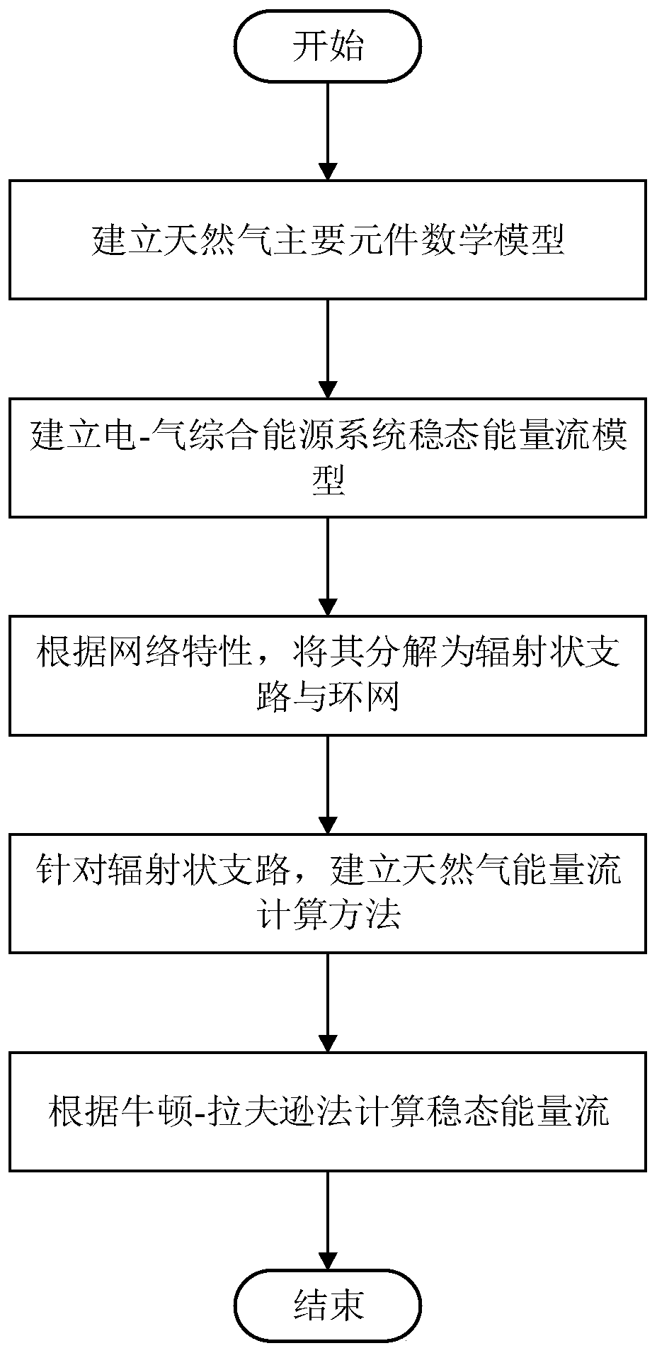
[0120] see Figure 1 to Figure 3 , a method for calculating the steady-state energy flow of an electric-gas integrated energy system based on topology analysis, which mainly includes the following steps:

[0121] 1) Establish a natural gas system model.

[0122] The natural gas system model mainly includes a natural gas pipeline lumped parameter model, a compressor model, a P2G (power-to-gas) model and a gas unit model.

[0123] 1.1) The main steps to establish the lumped parameter model of natural gas pipeline are as follows:

[0124] 1.1.1) Establish a steady-state model of the natural gas pipeline, namely:

[0125]

[0126]

[0127] In the formula, p k ,p m are the gas pressure at both ends of the natural gas pipeline; f km is the pipeline flow; sign(p k ,p m ) represents the actual flow direction of natural gas, when p k >p m When sign(p k ,p m )=1, when p k ≤p m When sign(p k ,p m )=-1; C km is the transmission performance parameter of the natural gas ...

Embodiment 2

[0231] A method for calculating the steady-state energy flow of an electric-gas integrated energy system based on topology analysis mainly includes the following steps:

[0232] 1) Establish a natural gas system model.

[0233] 2) Based on the KCL law, a steady-state energy flow model of the electricity-gas integrated energy system is established.

[0234] 3) Decompose the electricity-gas integrated energy system into radial branches and natural gas ring network.

[0235] 4) Calculate the natural gas energy flow of the radial branch.

[0236] 5) Calculate the steady-state energy flow according to the Newton-Raphson method. The steady-state energy flow includes power system power flow and natural gas ring network energy flow.

Embodiment 3

[0238] A steady-state energy flow calculation method for an electric-gas integrated energy system based on topology analysis, the main steps are shown in Example 2, wherein the natural gas system model mainly includes a natural gas pipeline lumped parameter model, a compressor model, a P2G model, and a gas-fired unit model .

[0239] 1) The main steps to establish the lumped parameter model of natural gas pipeline are as follows:

[0240] 1.1) Establish a steady-state model of the natural gas pipeline, namely:

[0241]

[0242]

[0243] In the formula, p k ,p m are the gas pressure at both ends of the natural gas pipeline; f km is the pipeline flow; sign(p k ,p m ) represents the actual flow direction of natural gas, when p k >p m When sign(p k ,p m )=1, when p k ≤p m When sign(p k ,p m )=-1; C km is the transmission performance parameter of the natural gas pipeline; C 0 is a constant; T b ,p b are the reference temperature and reference pressure, respec...


PUM


Abstract

The invention discloses an electricity-gas comprehensive energy system steady-state energy flow calculation method based on topological analysis. The method comprises the main steps: 1) establishing anatural gas system model; 2) based on a KCL law, establishing a steady-state energy flow model of the electricity-gas comprehensive energy system; 3) decomposing the electricity-gas comprehensive energy system into a radial branch and a natural gas looped network; 4) calculating the natural gas energy flow of the radial branch; and 5) calculating steady-state energy flow according to a Newton-Raphson method; wherein the steady-state energy flow comprises power system power flow and natural gas looped network energy flow. The method is suitable for the electricity-gas comprehensive energy system with a low natural gas system looped network rate, the network topology characteristics in the system are fully considered, the steady-state energy flow calculation efficiency is improved, and theconvergence range of solution is expanded.

Description

technical field [0001] The invention relates to the technical field of new energy power systems, in particular to a method for calculating the steady-state energy flow of an electric-gas integrated energy system based on topology analysis. Background technique [0002] With the non-renewable consumption of fossil energy and the increasingly prominent environmental problems, renewable energy has begun to emerge and move towards the center of the world stage. After unremitting efforts in recent years, countries such as Europe and the United States have taken the lead in carrying out a series of researches on comprehensive energy with electric energy as the core. The electric-gas integrated energy system is regarded as the basic framework of the future energy Internet. strategic deployment and theoretical research. The application of gas turbine and power-to-gas technology makes the relationship between the power system and the natural gas system more and more close, which in ...

Claims


Application Information

Patent Timeline
Patent Type & Authority Applications(China)
IPC IPC(8): G06F30/20G06Q50/06G06F113/14G06F111/10
CPCG06F30/20G06Q50/06G06F2113/14G06F2111/10
Inventor 任洲洋颜伟杨鑫
Owner CHONGQING UNIV
Learn More