Battery aging degree evaluation method and device
A kind of aging degree and battery technology, which is applied in the direction of measuring devices, measuring electricity, and measuring electrical variables, etc., can solve the problems of inability to form effective estimates, high labor costs, and low work efficiency, so as to improve processing speed and accuracy, reduce Amount of computation, comparatively high efficiency
- Summary
- Abstract
- Description
- Claims
- Application Information
AI Technical Summary
Problems solved by technology
Method used
Image
Examples
Embodiment 1
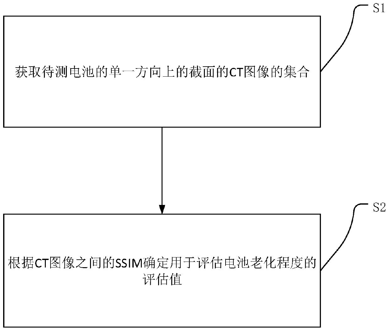
[0030] refer to figure 1 , showing a battery aging degree evaluation method, including:
[0031] S1. Obtain a collection of CT images of cross-sections in a single direction of the battery to be tested;
[0032] S2. Determine an evaluation value for evaluating battery aging according to the SSIM between CT images.
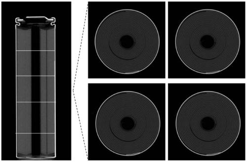
[0033] Such as figure 2 The CT scan example shown includes the overall scan image of the battery on the left and the cross-sectional scan image on the right; obtain the CT image of the cross-section of the battery to be tested in a single direction, for example, the horizontal concept is perpendicular to the electrode direction, and the vertical direction is The electrode direction, and so on; the CT process does not only scan one layer, but continues to scan along a certain direction (designated axis direction), so a large number of images will be generated, that is, a collection of CT images. According to the value of SSIM between different CT images, the eva...
Embodiment 2
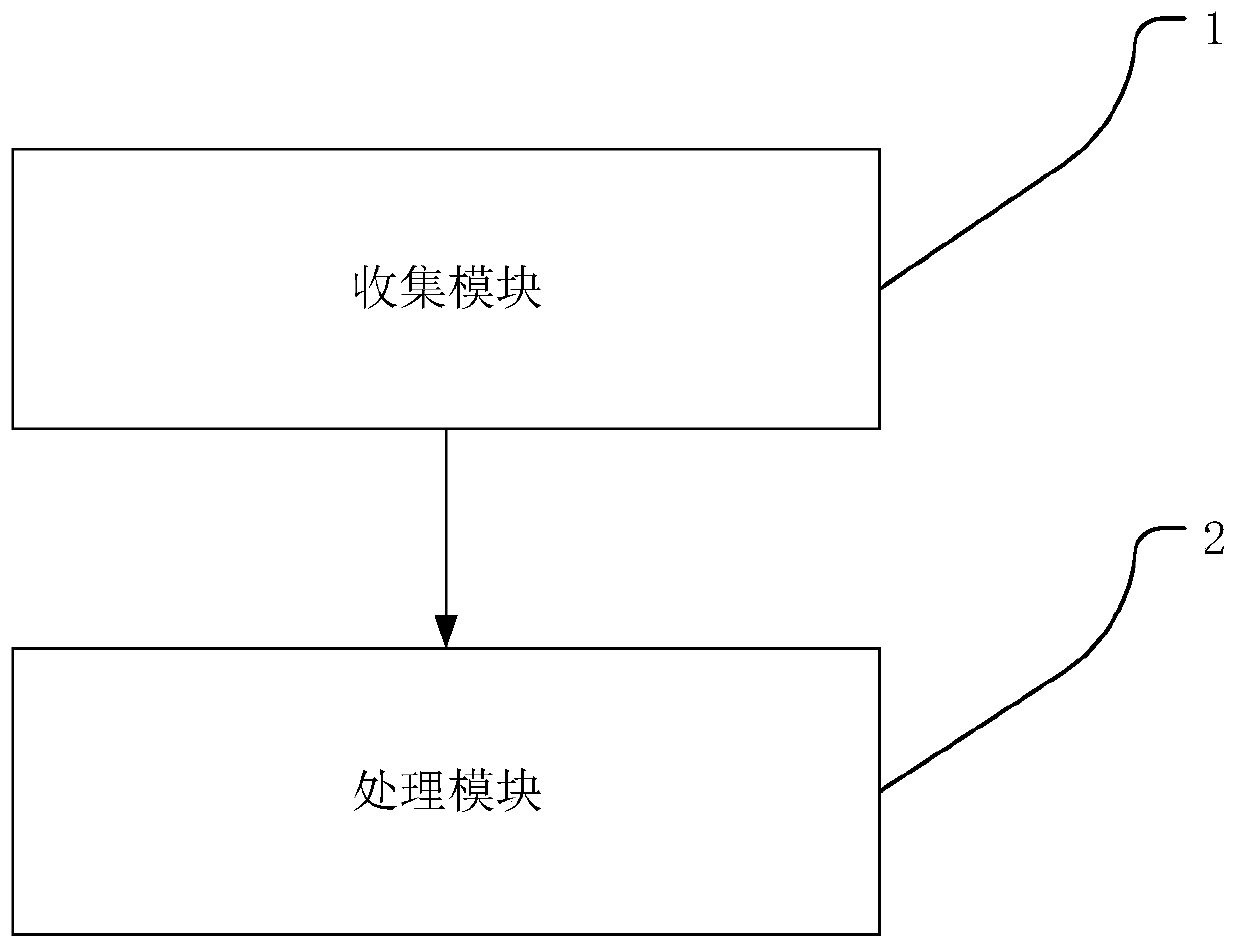
[0046] An embodiment of the present invention provides a battery aging evaluation device, including: a collection module 1, used to acquire a collection of CT images of sections in a single direction of the battery to be tested; a processing module 2, used to The SSIM between determines the evaluation value used to evaluate the degree of battery aging.
Embodiment 3
[0048] The purpose of this embodiment is to provide specific examples to explain the technical solution in Embodiment 1.
[0049] (1) The battery is scanned using the axial helical scanning method (that is, the method of rotating around the specified axis). Taking the Werth TomoScop XS instrument as an example, a battery can obtain a total of 2,500 CT images. It is worth noting that the spiral CT method allows the tube to rotate continuously and the bed surface to move in a directional manner, so that projection data can be collected without interruption. Therefore, one battery, after helical scanning, can obtain hundreds to thousands of CT images at different positions, and the number depends on the accuracy of the instrument.
[0050] (2) Extract 15 CT images equidistantly. For example, assuming that the CT equipment scans 1500 CT pictures, and the pictures are numbered according to the shooting sequence 1-1500, then one picture is selected every 100 numbers, so 15 CT pictu...
PUM
 Abstract
Description
Claims
Application Information
 - Generate Ideas
- Intellectual Property
- Life Sciences
- Materials
- Tech Scout
- Unparalleled Data Quality
- Higher Quality Content
- 60% Fewer Hallucinations
Browse by: Latest US Patents, China's latest patents, Technical Efficacy Thesaurus, Application Domain, Technology Topic, Popular Technical Reports.
© 2025 PatSnap. All rights reserved.Legal|Privacy policy|Modern Slavery Act Transparency Statement|Sitemap|About US| Contact US: help@patsnap.com


