


Quick Research
Generate reliable direction feasibility study reports for your R&D in just a few steps.

Technical Q&A
Discover and master advanced knowledge NOW. Basics, ideas, possibilities, all at once.

Find Solutions
As an expert in R&D theories, this can generate solutions to your technical problems instantly.

Evaluate Feasibility
Analyze your overall solution with one click, know your potential R&D risks in advance.

Monitor Landscape
Get weekly tech updates, stay abreast of the latest tech innovations and key insights.
Mounting structure and method for top surface spherical net rack
An installation structure and spherical technology, applied in special structures, building components, building structures, etc., can solve the problems of high material cost, labor consumption, and low on-site construction efficiency, reducing demolition and modification, saving labor, and eliminating potential safety hazards. Effect
- Summary
- Abstract
- Description
- Claims
- Application Information
AI Technical Summary
Problems solved by technology
Method used
Image

Examples
Embodiment 1
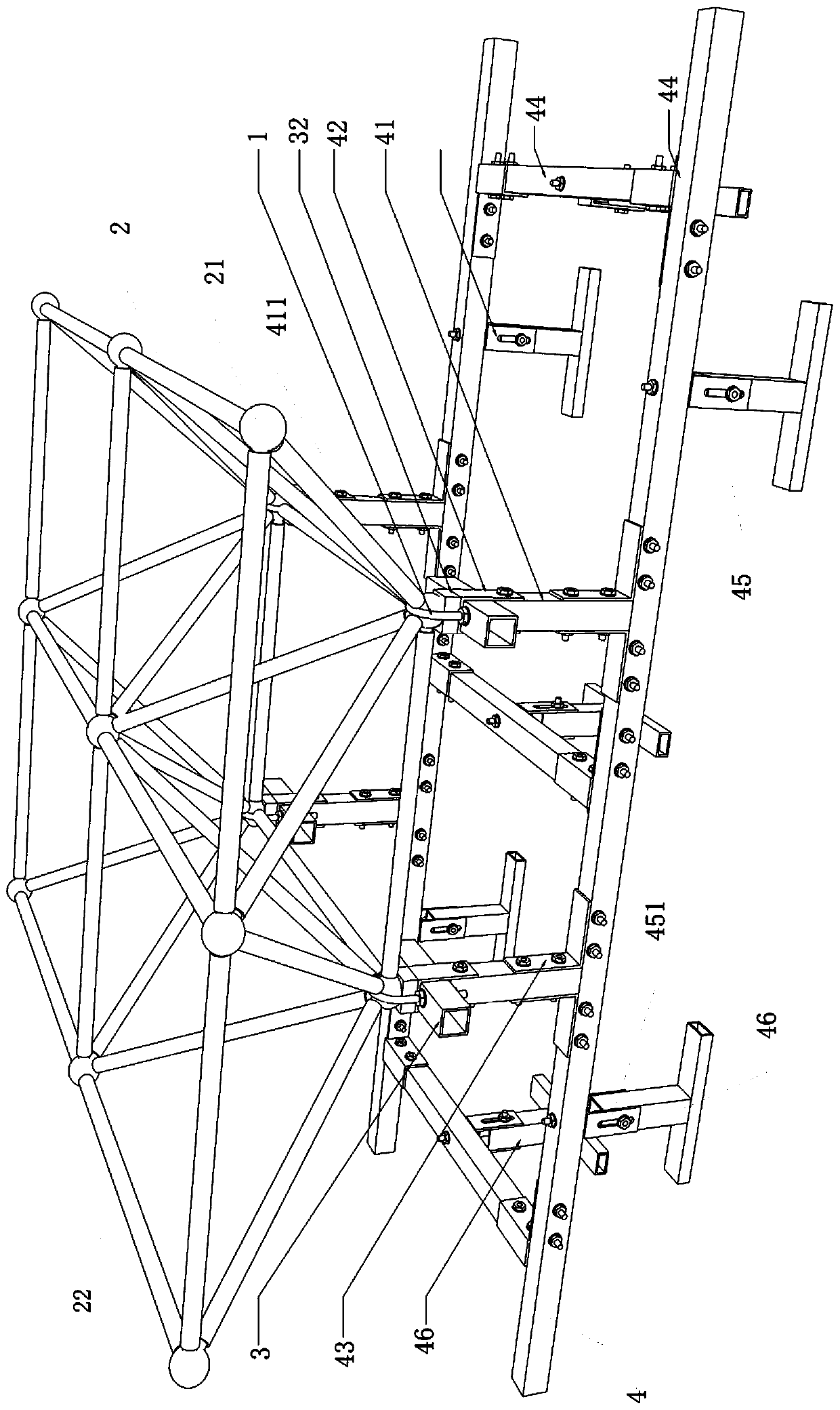
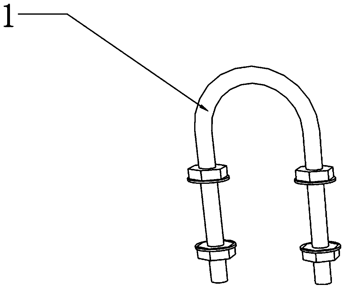
[0041] see Figure 1 to Figure 6 , the present embodiment provides an installation structure of a top spherical network frame, in which a U-shaped fixing part 1, a top spherical network frame 2, a first connecting frame 3 and a base frame 4 are mainly arranged, and the top spherical network frame 2 It includes a plurality of connecting rods 22 and a plurality of connecting balls 21 , and the connecting nodes of every two adjacent connecting rods 22 are located on the connecting balls 21 .
[0042] The U-shaped fixing part 1 is specifically a U-shaped hoop, and the U-shaped fixing part 1 is set on the connecting ball 21 of the top surface spherical grid frame 2, and the first connecting frame 3 is connected with the two ends of the U-shaped fixing part 1 , the U-shaped fixing member 1 presses the connecting ball 21 on the first connecting frame 3 , and the base frame 4 is connected with the first connecting frame 3 .
[0043] continue to see Figure 1 to Figure 6 , the first ...
Embodiment 2
[0054] see Figure 1 to Figure 6 , the figure shows the installation structure of a top surface spherical network frame provided by the second embodiment of the present invention. This embodiment further makes the following technical solutions as improvements on the basis of the above-mentioned embodiments: the base frame 4 Specifically connect to the first connecting frame 3 through the second connecting frame 41, and connect under the premise that the second connecting frame 41 is perpendicular to the first connecting frame 3.
[0055] see figure 1 , the second connecting frame 41 is a square tube, the U-shaped connecting piece 42 is sleeved on the first connecting frame 3, and the end of the U-shaped connecting piece 42 is connected to the side of the second connecting frame 41 through bolts and nuts. Therefore, the connection between the second connecting frame 41 and the first connecting frame 3 is realized without welding.
Embodiment 3
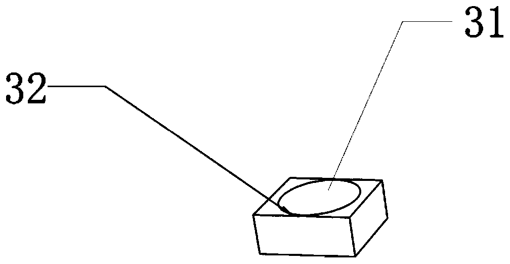
[0057] see Figure 1 to Figure 6 , the figure shows the installation structure of a top surface spherical network frame provided by the third embodiment of the present invention. On the basis of the above-mentioned embodiments, this embodiment further makes the following technical solutions as improvements: the second The connecting frame 41 is perpendicular to the basic frame 4, and the second connecting frame 41 is connected to the square tube unit 44 of the basic frame 4 through the L-shaped connector 43, and the side flange of the L-shaped connecting part 43 is connected to the second connecting frame 41 by bolts and nuts One side of the L-shaped connector 43 also has a connecting plate 431 connected to the side of the square tube unit 44, and the connecting plate 431 is connected to the square tube unit 44 through bolts and nuts. Therefore, the connection between the second connecting frame 41 and the base frame 4 is realized without welding.
PUM
 Abstract
Description
Claims
Application Information
 - R&D Engineer
- R&D Manager
- IP Professional
- Industry Leading Data Capabilities
- Powerful AI technology
- Patent DNA Extraction
Browse by: Latest US Patents, China's latest patents, Technical Efficacy Thesaurus, Application Domain, Technology Topic, Popular Technical Reports.
© 2024 PatSnap. All rights reserved.Legal|Privacy policy|Modern Slavery Act Transparency Statement|Sitemap|About US| Contact US: help@patsnap.com