Biochemical treatment system and process for landfill leachate

A landfill leachate and biochemical treatment technology, which is applied in the direction of polluted groundwater/leachate treatment, biological treatment equipment, biological water/sewage treatment, etc., can solve the problem of insufficient denitrification reaction in anoxic pools and unfavorable anoxic pools. Mixed reaction, high cost of sludge treatment and disposal, to achieve the effect of promoting the proliferation of nitrifying bacteria, reducing disposal costs, and reducing residence time

Pending Publication Date: 2020-08-21
HUNAN CAPITAL INVESTMENT CO LTD
View PDF0 Cites 2 Cited by
  • Summary
  • Abstract
  • Description
  • Claims
  • Application Information

AI Technical Summary

Problems solved by technology

[0006] 1. The growth rate of anaerobic bacteria is slow, and the effect of anaerobic treatment is poor;
[0007] 2. The denitrification reaction in the anoxic pool is not sufficient, and the denitrification efficiency of the anoxic pool is not high;
[0008] 3. The sludge from the secondary settling tank flows back to the anaerobic tank, and the hypoxia time is too long, resulting in a decrease in the activity of nitrifying bacteria, and the removal rate of ammonia nitrogen is not high enough when treating landfill leachate;
[0009] 4. There are relatively many mechanical equipment such as mixers, and the maintenance workload is large and the power consumption is high;
[0010] 5. The water in and out of the anoxic pool adopts the form of an orifice or a channel, which is not conducive to the full mixing reaction of the anoxic pool;
[0011] 6. The concentration of influent organic matter is high, the amount of residual sludge is large, and the cost of sludge treatment and disposal is high

Method used


Image

  • Biochemical treatment system and process for landfill leachate
  • Biochemical treatment system and process for landfill leachate
  • Biochemical treatment system and process for landfill leachate

Examples


Embodiment 1

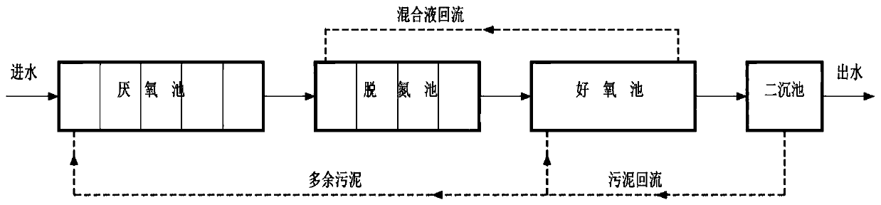
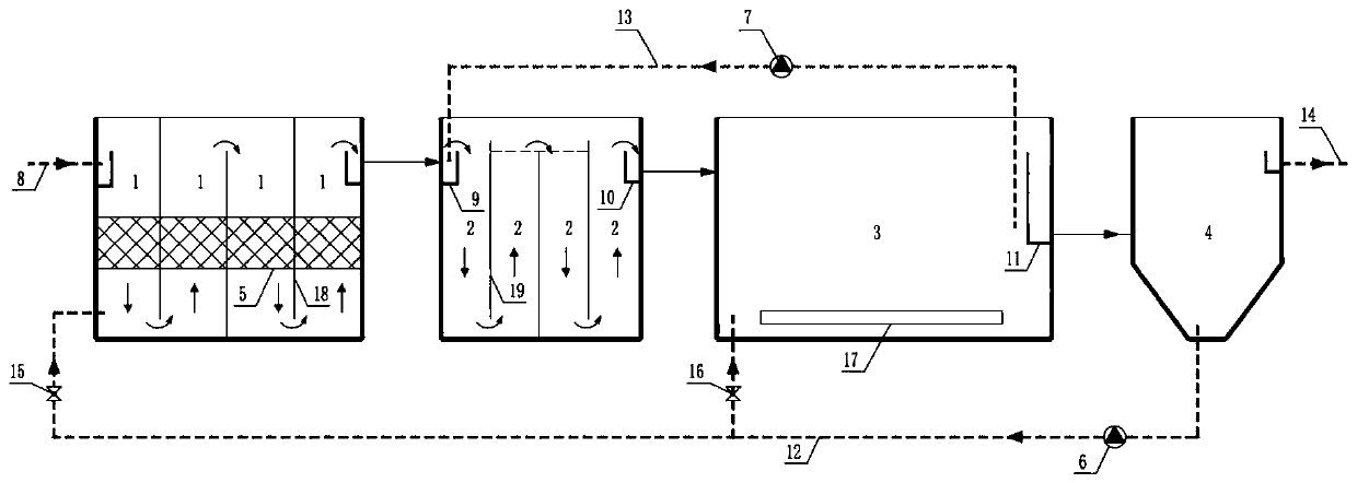
[0038] Such as figure 2 The shown biochemical treatment system for landfill leachate includes an anaerobic pool 1, a denitrification pool 2, an aerobic pool 3, and a secondary sedimentation pool 4 connected end to end in sequence according to the water flow direction of the landfill leachate. The settling tank 4 is connected with the water inlet pipe 8 and the water outlet pipe 14 respectively. The anaerobic tank 1 and the denitrification tank 2 are divided into several grids along the direction of water flow, and the aerobic tank 3 is connected back to the The water inlet end of the denitrification tank 2 and the bottom of the secondary settling tank 4 are also provided with a sludge return pipeline 12, and the other end of the sludge return pipeline 12 is divided into two branches, which are connected with the aerobic tank 3 and the anaerobic tank respectively. 1 connected to the water inlet.

[0039] Fillers 5 are arranged in each grid of the anaerobic tank 1, so that ana...


PUM


Abstract

The invention discloses a biochemical treatment system and process for landfill leachate. The biochemical treatment system is formed by sequentially connecting an anaerobic tank, a denitrification tank, an aerobic tank and a secondary sedimentation tank end to end, wherein the anaerobic tank and the secondary sedimentation tank respectively communicate with a water inlet pipeline and a water outlet pipeline; the anaerobic tank and the denitrification tank are respectively divided into a plurality of grids along a water flow direction; the aerobic tank is connected to a water inlet end of the denitrification tank through a mixed liquid return pipeline positioned at the water outlet end of the aerobic tank; a sludge return pipeline is arranged at the bottom of the secondary sedimentation tank; and the other end of the sludge return pipeline is divided into two branches which respectively communicate with the water inlet ends of the aerobic tank and the anaerobic tank. The biochemical treatment process for landfill leachate realized on the basis of the system can effectively remove COD, ammonia nitrogen and total nitrogen pollutants in the landfill leachate.

Description

technical field [0001] The invention relates to a sewage treatment system, in particular to a landfill leachate biochemical treatment system and process. It belongs to the technical field of sewage treatment. Background technique [0002] Domestic garbage leachate is a kind of sewage with complex components and unbalanced nutrients. It has the characteristics of high COD, high ammonia nitrogen, and high total nitrogen. And the total nitrogen concentration is as high as about 1500-2000mg / L. In recent years, domestic and foreign leachate treatment mainly takes biochemical treatment as the main process. The biochemical treatment process relies on the activity of microorganisms in the reactor, that is, activated sludge. It is necessary to carefully control various environmental conditions in the reactor to maintain the stable operation of the activated sludge microbial system, although the growth conditions of many microorganisms have been studied for a long time , but for th...

Claims


Application Information

Patent Timeline
Patent Type & Authority Applications(China)
IPC IPC(8): C02F9/14C02F103/06
CPCC02F3/305C02F1/52C02F2103/06C02F2203/006C02F2301/046C02F2209/08C02F2209/14C02F2209/16
Inventor 张哲麟黎青松王荣娟郭会超李卫平刘月曼黄东
Owner HUNAN CAPITAL INVESTMENT CO LTD
Why Eureka
Try Eureka