
Inductive charging system and method with switchable constant current-constant voltage output modes

A technology of inductive charging and constant voltage output, which is applied in the direction of output power conversion device, DC power input conversion to DC power output, AC power input conversion to DC power output, etc., to improve charging efficiency, avoid reactive power circulation, Guaranteed effectiveness and reliability

Active Publication Date: 2020-08-18
NANJING UNIV OF POSTS & TELECOMM
View PDF2 Cites 8 Cited by
  • Summary
  • Abstract
  • Description
  • Claims
  • Application Information

AI Technical Summary

Problems solved by technology

[0009] The purpose of the present invention is to provide a constant current-constant voltage output mode switchable inductive charging system and method to solve the problem in the prior art of how to adjust the output on the primary side without occupying the limited space of the secondary side, and at the same time Does not rely on real-time wireless feedback, thus taking into account the practicality and reliability of the system

Method used


Image

  • Inductive charging system and method with switchable constant current-constant voltage output modes
  • Inductive charging system and method with switchable constant current-constant voltage output modes
  • Inductive charging system and method with switchable constant current-constant voltage output modes

Examples


Embodiment

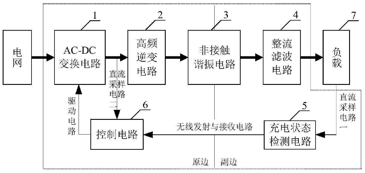
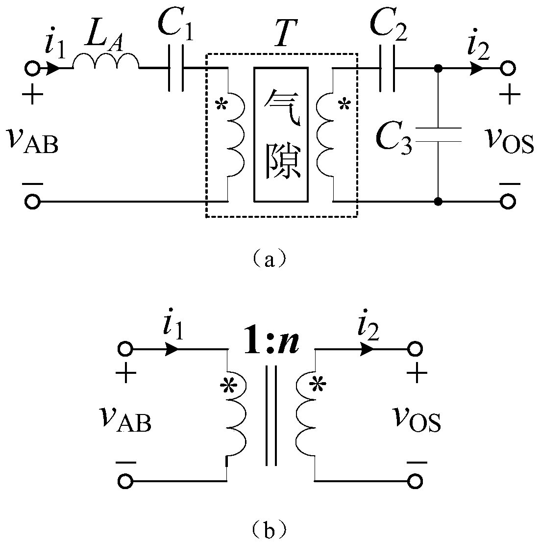
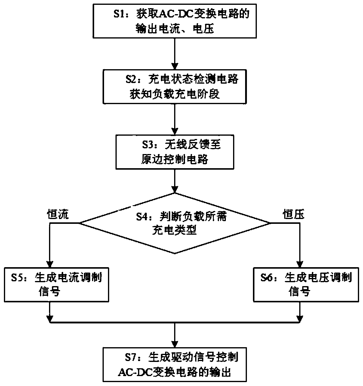
[0053] A constant current-constant voltage output mode switchable inductive charging system, such as figure 1 , including AC-DC conversion circuit 1, high-frequency inverter circuit 2, non-contact resonant circuit 3, rectification and filtering circuit 4, charging state detection circuit 5 and control circuit 6. The input end of the AC-DC conversion circuit 1 is connected to the grid, and the output end of the AC-DC conversion circuit 1 is connected to the high-frequency inverter circuit 2, and the high-frequency inverter circuit 2 is connected to the input end of the non-contact resonance circuit 3, and the non-contact resonance The output end of the circuit 3 is connected to the load through the rectification and filtering circuit 4, the charging state detection circuit 5 is connected to the load through the DC sampling circuit 1, the charging state detection circuit 5 is connected to the control circuit 6 through the wireless transmitting and receiving circuit, and the contr...


PUM


Abstract

The invention provides an inductive charging system and method with switchable constant current-constant voltage output modes. The system comprises an AC-DC conversion circuit, a high-frequency inverter circuit, a non-contact resonance circuit, a rectification filter circuit, a charging state detection circuit and a control circuit. The high-frequency inverter circuit is used for providing a high-frequency alternating-current power supply for the non-contact resonance circuit, the rectifying and filtering circuit converts the alternating current output of the non-contact resonance circuit intothe direct current for supplying power to a load, and the charging state detection circuit obtains the current charging stage information of the load. The control circuit obtains the current output direct current and voltage of the AC-DC conversion circuit, and sends a control signal to the AC-DC conversion circuit through the drive circuit according to the current charging stage information of the load, thereby achieving the control of the output of the AC-DC conversion circuit. According to the invention, the output current and voltage of the AC-DC conversion circuit are controlled at the primary side in a closed-loop manner, the charging current and voltage of the secondary side load can be accurately controlled, the practicability and reliability of the system can be ensured, and thecharging efficiency is improved.

Description

technical field [0001] The invention relates to a constant current-constant voltage output mode switchable inductive charging system and method. Background technique [0002] Inductive wireless power supply technology uses the mutual coupling of the magnetic field between the primary and secondary sides of the non-contact transformer to realize wireless transmission of electric energy through air, water and other media. Since there is no direct contact between the power transmitting end on the primary side and the power receiving end on the secondary side, it has been used in some special occasions (such as charging of human implanted equipment, power supply in mines, oil fields, and underwater). Wide range of applications. At the same time, the application of wireless power supply technology in daily life, such as wireless charging of portable devices such as mobile phones and tablet computers, and wireless power supply in tailless household appliances, also provides human...

Claims


Application Information

Patent Timeline
IPC IPC(8): H02J7/04H02J7/02H02J50/10H02M7/217H02M3/335H02M1/12
CPCH02J50/10H02M7/217H02M3/33523H02M1/12H02M1/0009Y02T90/14
Inventor 侯佳陈乾宏季骏
Owner NANJING UNIV OF POSTS & TELECOMM
Learn More