Oil pumping unit

A technology of pumping unit and base, which is applied in the direction of exploitation fluid, wellbore/well parts, earthwork drilling and production, etc. It can solve the problems of increasing power loss, heavy adjustment workload, increasing motor gear pressure, etc. Achieve the effect of reducing starting power and improving energy utilization

Inactive Publication Date: 2020-08-18
胡立宇
View PDF0 Cites 1 Cited by
  • Summary
  • Abstract
  • Description
  • Claims
  • Application Information

AI Technical Summary

Problems solved by technology

[0003] The purpose of the present invention is to provide a pumping unit to solve the problem that the donkey head reciprocates up and down when the existing beam pumping unit proposed in the above-mentioned background technology is in operation, and the inertial load increases when the donkey head swings. The pressure on the motor gear also increases the power loss and reduces the energy utilization efficiency of the beam pumping unit, and the starting power of the existing beam pumping unit is about twice the normal power. The utilization rate of the drive motor power is further reduced. Due to the complex stratum structure, oil production and water injection cannot completely fill the stratum gap after oil production, which will inevitably lead to partial ground subsidence, causing the pumping unit to skew. The existing pumping unit is usually not There is a skew compensation structure. Once the pumping unit is skewed, the engineering personnel need to adjust the height of each point of the base. This adjustment method requires a lot of work and is very inconvenient to use.

Method used


Image

  • Oil pumping unit
  • Oil pumping unit
  • Oil pumping unit

Examples


Embodiment Construction

[0024] The following will clearly and completely describe the technical solutions in the embodiments of the present invention with reference to the accompanying drawings in the embodiments of the present invention. Obviously, the described embodiments are only some, not all, embodiments of the present invention. Based on the embodiments of the present invention, all other embodiments obtained by persons of ordinary skill in the art without making creative efforts belong to the protection scope of the present invention.

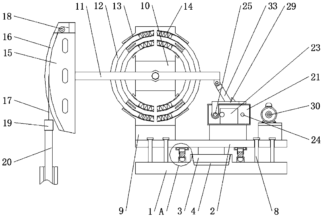
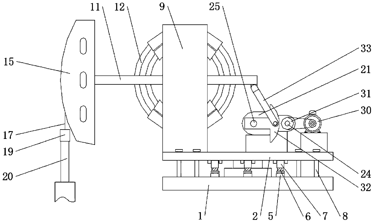
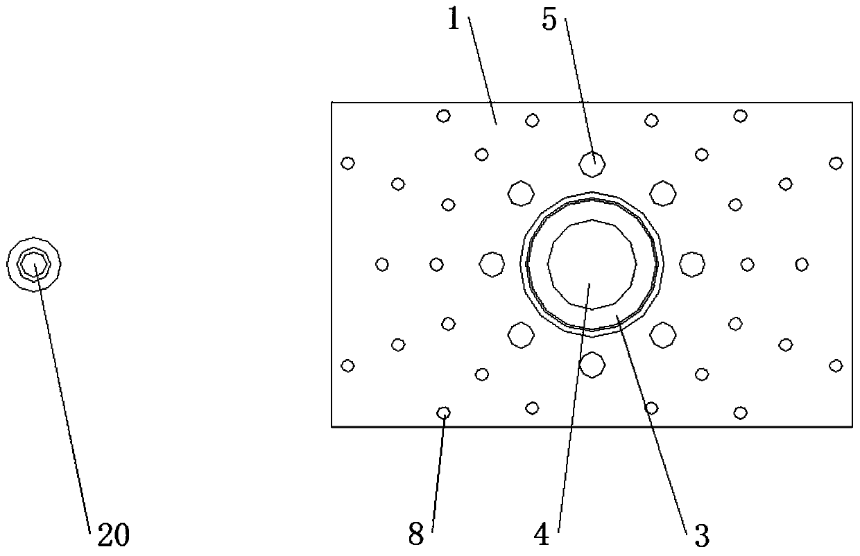
[0025] see Figure 1-6 , the present invention provides a technical solution: a pumping unit, such as figure 1 , image 3 and Figure 6 As shown, a base 2 is provided above the base 1, and a universal ring 3 is provided at the bottom of the base 2, and a screw 8 is evenly threaded on the base 2, and the screw 8 supports the base 2, so that the base 2 and the base 1 are kept The effect of spacing, the centerline of the universal ring 3, the centerline of the...


PUM


Abstract

The invention discloses an oil pumping unit. The oil pumping unit comprises a base, a screw and a connecting rod. A seat is arranged on the upper part of the base, a universal ring is arranged at thebottom of the seat, and a ring groove is formed in the top of the base. The universal ring is arranged in the ring groove, a connecting piece is rotatably arranged on the upper surface of the base, the top of the connecting piece is rotatably connected with a stud, the upper end of the stud is in threaded connection with the lower end of a rotating screw sleeve, the upper end of the rotating screwsleeve is rotatably connected to the lower surface of the seat, the lower end of the screw penetrates the seat and is attached to the upper surface of the base, a bracket is arranged at the upper left of the seat, and an opening is formed in the middle of the bracket. The pumping unit is provided with a sliding rod, a sliding groove and a compression spring. When a walking beam rotates, the sliding rod on one side of the rotation direction of the walking beam slides into the sliding groove, at the same time, the compression spring is extruded, and the compression spring absorbs kinetic energyand reduces the inertial load during rotation of the walking beam; and until the walking beam rotates in the reverse direction, the compression spring releases the kinetic energy, and the effects ofreducing the damage to the capacity and reducing the pressure of the inertial load on a gear are achieved.

Description

technical field [0001] The invention relates to the technical field of oil pumping units, in particular to an oil pumping unit. Background technique [0002] The pumping unit is a kind of machinery used to exploit crude oil in the formation. Among them, the beam pumping unit is widely used because of its simple structure and high stability. Reciprocating motion, while the inertial load when the donkey head swings increases the pressure on the motor gear, and also increases the power loss, reducing the energy utilization efficiency of the beam pumping unit, and the existing beam pumping unit The start-up power of the engine is more than double the normal power, which further reduces the utilization rate of the drive motor power. Due to the complex stratum structure, oil production and water injection cannot completely fill the stratum gap after oil production, which will inevitably lead to partial ground subsidence, making The pumping unit is skewed. The existing pumping uni...

Claims


Application Information

Patent Timeline
Patent Type & Authority Applications(China)
IPC IPC(8): E21B43/00
CPCE21B43/127
Inventor 胡立宇
Owner 胡立宇
Why Eureka
Try Eureka