
Metal plate machining mold

A machining and mold technology, applied in the field of sheet metal processing, can solve the problems of reducing equipment use occasions and efficiency, reducing the types of bending and forming of sheet metal parts, and reducing the bending flexibility of sheet metal parts, so as to reduce the use of Occasions and efficiency of use, increase in variety, and effects of improving the occasion and efficiency of use

Inactive Publication Date: 2020-08-18
李美冬
View PDF0 Cites 0 Cited by
  • Summary
  • Abstract
  • Description
  • Claims
  • Application Information

AI Technical Summary

Problems solved by technology

[0005] The invention can solve the problem that the existing equipment cannot realize accurate bending of different positions of the sheet metal parts when performing bending processing on the sheet metal parts, thereby reducing the types of bending and forming of the sheet metal parts and reducing the cost of the sheet metal parts. The flexibility of bending, and the sheet metal parts cannot be slid when the sheet metal parts are bent, and the sheet metal parts tend to be too thin when bending, which reduces the uniformity of the thickness of the sheet metal parts. At the same time, it cannot Realize the change of the bending angle of sheet metal parts, thereby reducing the types of sheet metal parts processing, reducing the use occasions and efficiency of equipment and other problems

Method used


Image

  • Metal plate machining mold
  • Metal plate machining mold
  • Metal plate machining mold

Examples


Embodiment Construction

[0030] The embodiments of the present invention will be described in detail below with reference to the accompanying drawings, but the present invention can be implemented in many different ways defined and covered by the claims.

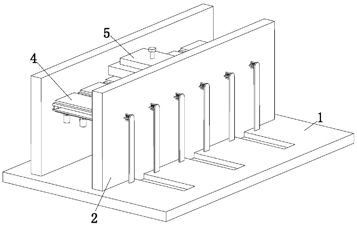
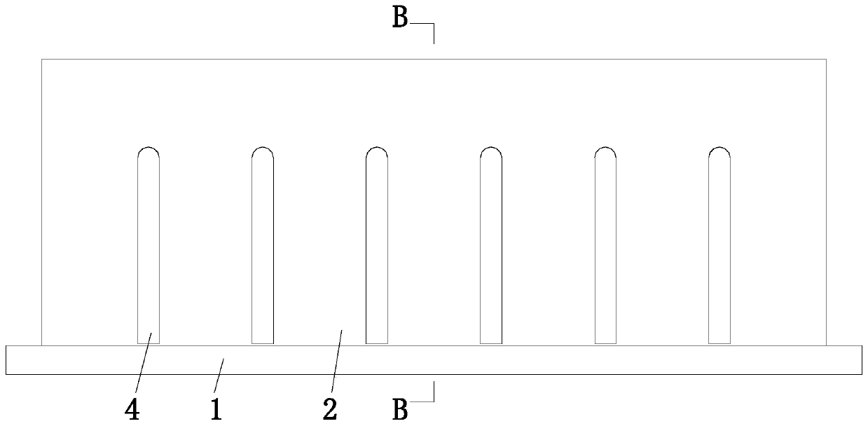
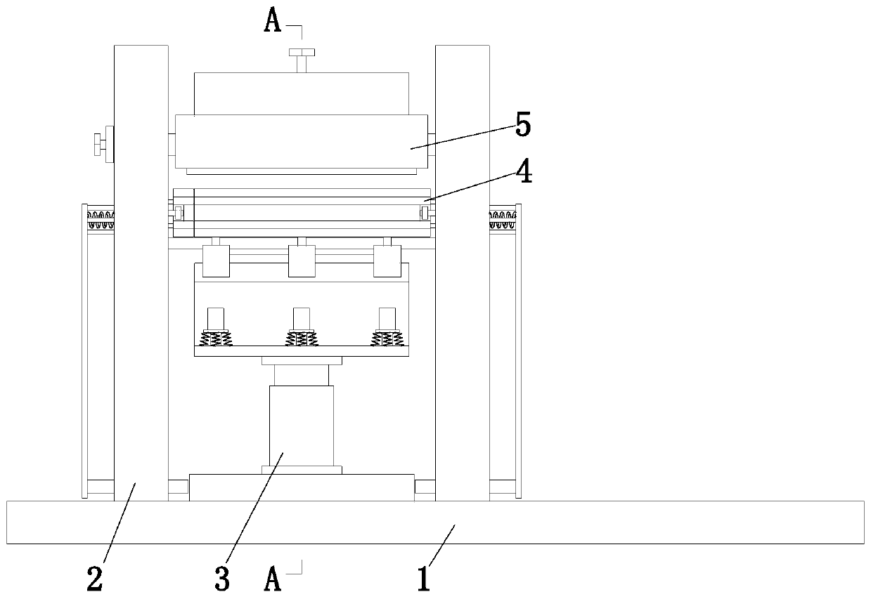
[0031] Such as Figure 1 to Figure 9 As shown, a sheet metal machining mold includes a base plate 1, a support plate 2, a lifting device 3, a clamping device 4 and an adjustment device 5. The upper end of the base plate 1 is symmetrically provided with a support plate 2 front and back, and the rear support The plate 2 is installed on the bottom plate 1, the front supporting plate 2 is slidingly connected with the bottom plate 1, a lifting device 3 is arranged between the supporting plates 2, the lifting device 3 is slidingly connected with the bottom plate 1, and a clamping device is arranged above the lifting device 3 The device 4, the clamping device 4 is installed on the support plate 2 through the pin shaft, and the adjustment device 5 is arrang...


PUM


Abstract

The invention relates to a metal plate machining mold. The mold comprises a bottom plate, supporting plates, a jacking device, a clamping device and an adjusting device, the supporting plates are mounted on the upper end of the bottom plate in a front and back symmetry manner, the supporting plate on the back is mounted on the bottom plate, the supporting plate on the front is in sliding connection with the bottom plate, the jacking device is mounted between the supporting plates, and the problems that when an existing device carries out bending treatment on a metal plate part, different positions of the metal plate part cannot be subjected to precise bending, the metal plate part bending forming kind is reduced, the bending flexibility of the metal plate part is reduced, when the metal plate part is bent, the metal plate part cannot slide, during metal plate part bending, the too thin phenomenon is prone to appearing, the metal plate part thickness uniformity is reduced, meanwhile, the metal plate part bending angle cannot be changed, the metal plate machining kind is reduced, and the use occasion and the use efficiency of equipment are reduced.

Description

technical field [0001] The invention relates to the technical field of sheet metal processing, in particular to a sheet metal machining mold. Background technique [0002] Sheet metal parts refer to products processed by sheet metal technology. Sheet metal parts are processed by laser cutting, heavy processing, metal bonding, metal drawing, plasma cutting, precision welding, roll forming, sheet metal bending forming, die forging, etc. Manufactured, sheet metal parts have the characteristics of light weight, high strength, electrical conductivity, low cost, and good mass production performance, and have been widely used in electronic appliances, communications, automobile industry, medical equipment and other fields. [0003] At present, when bending sheet metal parts, there are usually the following deficiencies: 1. Existing equipment cannot realize accurate bending of different positions of sheet metal parts, thereby reducing the types of bending and forming of sheet metal ...

Claims


Application Information

Patent Timeline
Patent Type & Authority Applications(China)
IPC IPC(8): B21D11/00B21D11/22
CPCB21D11/00B21D11/22
Inventor 李美冬伍勇军夏可欣
Owner 李美冬
Learn More