
Vessel Sealer and Divider

Active Publication Date: 2010-06-10
TYCO HEALTHCARE GRP LP
View PDF99 Cites 99 Cited by
  • Summary
  • Abstract
  • Description
  • Claims
  • Application Information

AI Technical Summary

Benefits of technology

[0020]In a further embodiment, at least one of the jaw members may be made from a stiffer material, thereby reducing the flexibility of the jaw member, and improving seal performance. The distal end of the end effector assembly may have a variety of shapes including a blunt end. In still another embodiment, at least one of the jaw members has a texturized surface for facilitating grasping and retaining of tissue. Stop members may be included on at least one of the jaw members to create a gap between the jaw members when they are disposed in the second position. The jaw members may also be coated with a nonstick material.

Problems solved by technology

Smaller cannulas are usually preferred, which, as can be appreciated, ultimately presents a design challenge to instrument manufacturers who attempt to find ways to make endoscopic instruments that fit through the smaller cannulas.
Due to the inherent spatial considerations of the surgical cavity, surgeons often have difficulty suturing vessels or performing other traditional methods of controlling bleeding, e.g., clamping and / or tying-off transected blood vessels.
However, if a larger vessel is ligated, it may be necessary for the surgeon to convert the endoscopic procedure into an open-surgical procedure and thereby abandon the benefits of endoscopic surgery.
Below this range, the seal may shred or tear and above this range the lumens may not be properly or effectively sealed.
This presents a design challenge because the jaw members are typically affixed with pins which are positioned to have small moment arms with respect to the pivot of each jaw member.
A large force, coupled with a small moment arm, is undesirable because the large forces may shear the pins.
Increasing the closure forces between electrodes may have other undesirable effects, e.g., it may cause the opposing electrodes to come into close contact with one another which may result in a short circuit and a small closure force may cause premature movement of the tissue during compression and prior to activation.
As can be appreciated, relying on a surgeon to manually provide the appropriate closure force within the appropriate range on a consistent basis would be difficult and the resultant effectiveness and quality of the seal may vary.

Method used


Image

  • Vessel Sealer and Divider
  • Vessel Sealer and Divider
  • Vessel Sealer and Divider

Examples


Embodiment Construction

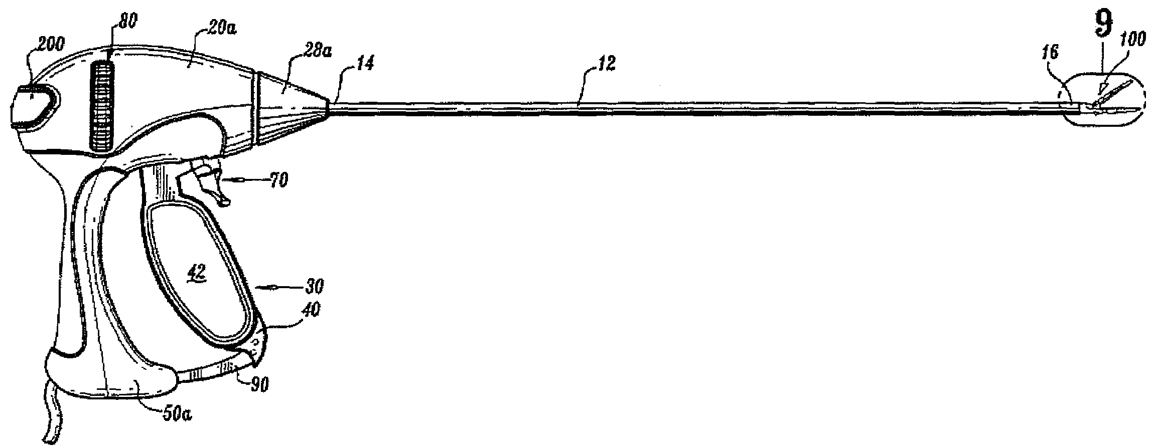
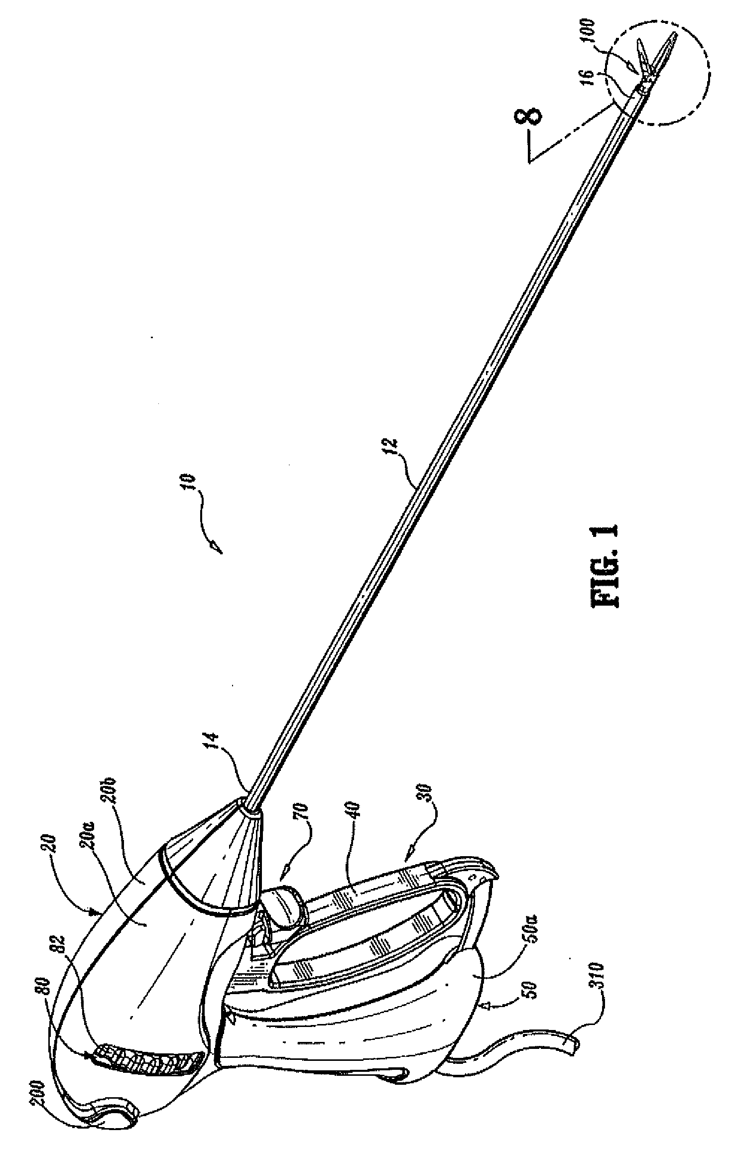
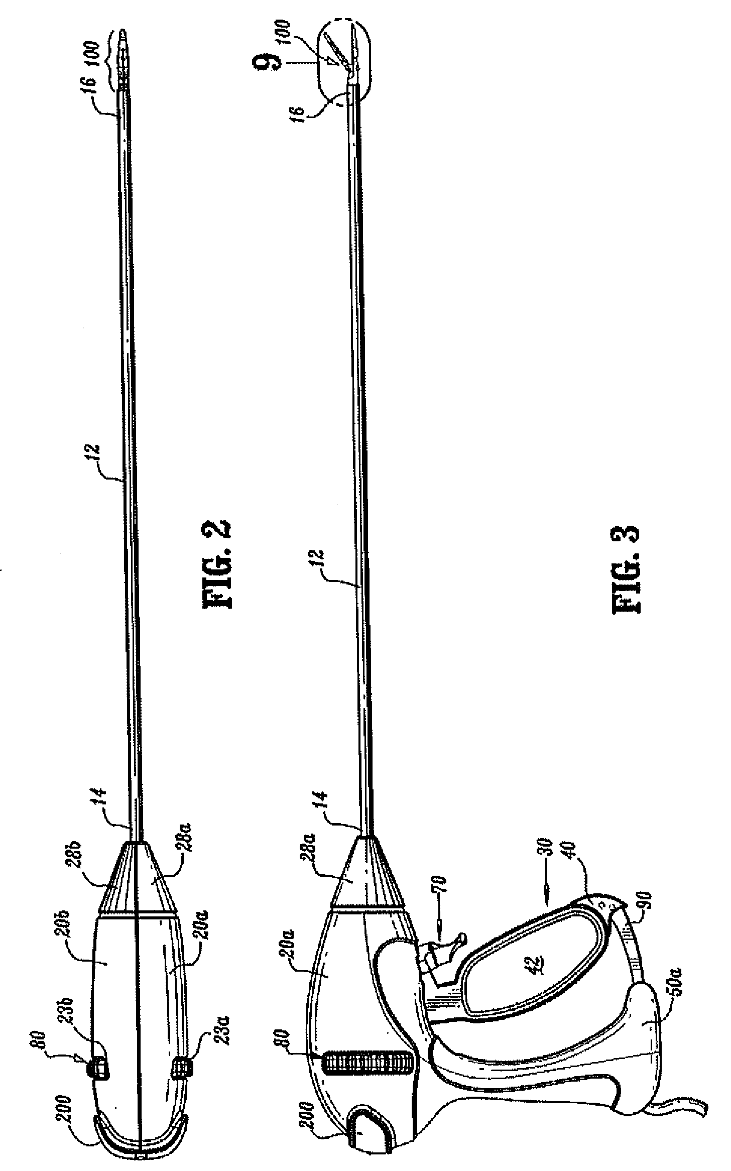
[0077]The present disclosure describes an endoscopic bipolar forceps 10 including multiple assemblies, i.e., a handle assembly, a rotating assembly, a trigger assembly, and an end effector assembly. It will be understood that other assemblies may be substituted for those described herein.

[0078]In particular, two embodiments of an end effector assembly, 100 and 500, are described herein. It will be understood that each end effector assembly, 100 and 500, may be substituted for one another without modification to the forceps 10 in any other way.

[0079]Turning now to FIGS. 1-3, one embodiment of an endoscopic bipolar forceps 10 is shown for use with various surgical procedures and generally includes a housing 20, a handle assembly 30, a rotating assembly 80, a trigger assembly 70 and an end effector assembly 100 which mutually cooperate to grasp, seal and divide tubular vessels and vascular tissue 420 (FIG. 36). Although the majority of the figure drawings depict a bipolar forceps 10 fo...


PUM


Abstract

An endoscopic bipolar forceps includes a housing and a shaft, the shaft having an end effector assembly at a distal end thereof, which includes two jaw members for grasping tissue therebetween. Each jaw member is adapted to connect to an electrosurgical energy source, enabling them to affect a tissue seal to tissue held therebetween. A drive assembly is included within the housing for moving the jaw members. A movable handle is also included, such that movement of the handle actuates the drive assembly to move the jaw members relative to each other. A knife channel is included within the end effector configured to allow reciprocation of a knife blade within the knife channel. The knife blade includes a proximal edge adapted to engage a proximal edge of the end effector to impede translation of the knife blade when the jaw members are in an open configuration and the knife blade is retracted within the end effector assembly.

Description

BACKGROUND[0001]1. Technical Field[0002]The present disclosure relates to an electrosurgical forceps and more particularly, the present disclosure relates to an endoscopic bipolar electrosurgical forceps for sealing and / or cutting tissue.[0003]2. Background of Related Art[0004]Electrosurgical forceps utilize both mechanical clamping action and electrical energy to effect hemostasis by heating the tissue and blood vessels to coagulate, cauterize and / or seal tissue. As an alternative to open forceps for use with open surgical procedures, many modern surgeons use endoscopes and endoscopic instruments for remotely accessing organs through smaller, puncture-like incisions. As a direct result thereof, patients tend to benefit from less scarring and reduced healing time,[0005]Endoscopic and / or laparoscopic instruments are inserted into the patient through a cannula, or a port, which has been made with a trocar. Typical sizes for cannulas range from three millimeters to twelve millimeters. ...

Claims


Application Information

Patent Timeline
IPC IPC(8): A61B18/18
CPCA61B18/1445A61B2018/00083A61B2018/00345A61B2018/00404A61B2018/1455A61B2018/00619A61B2018/0063A61B2018/1412A61B2018/00601A61B2018/00077
Inventor OLSON, JESSICA E.UNGER, JEFFREY R.
Owner TYCO HEALTHCARE GRP LP
Learn More