
Horizontal screw discharge sedimentation centrifuge and its feed tube

A settling centrifuge and horizontal screw technology, which is applied to centrifuges with rotating drums, centrifuges, etc., can solve the problems affecting the centrifugal separation effect and turbulent flow, and achieve power saving, smooth discharge, and deflection sex reducing effect

Active Publication Date: 2017-06-27
GREEN WATER SEPARATION EQUIP
View PDF9 Cites 1 Cited by
  • Summary
  • Abstract
  • Description
  • Claims
  • Application Information

AI Technical Summary

Problems solved by technology

At present, the shape of the discharge port of the feed tube body is designed to be a perfect circle, and the suspension is discharged straight from the perfect circular discharge port. Although it can meet the requirements of the discharge to a certain extent, it will cause problems. The discharge area in the liquid pool is undergoing the process of sedimentation and separation to form deflection, which causes different degrees of turbulent flow and affects the effect of centrifugal separation.

Method used


Image

  • Horizontal screw discharge sedimentation centrifuge and its feed tube
  • Horizontal screw discharge sedimentation centrifuge and its feed tube
  • Horizontal screw discharge sedimentation centrifuge and its feed tube

Examples


Embodiment Construction

[0021] The present invention will be further described below in conjunction with the accompanying drawings and specific embodiments, so that those skilled in the art can better understand the present invention and implement it, but the examples given are not intended to limit the present invention.

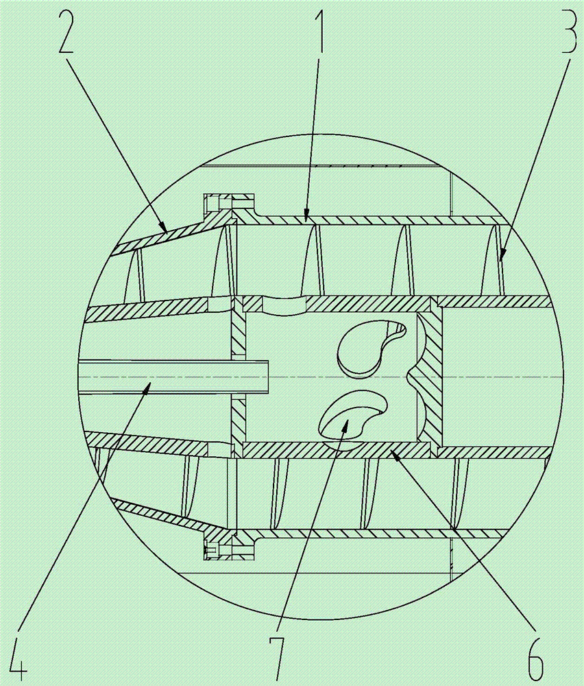
[0022] like figure 1 Shown is a schematic structural view of an embodiment of the horizontal screw discharge decanter centrifuge of the present invention. The horizontal spiral unloading decanter centrifuge of this embodiment includes a straight drum 1, a conical drum 2 installed at one end of the straight drum 1, and a spiral body arranged in the conical drum 2, and a spiral body is arranged on the outer peripheral wall of the spiral body. The blade 3 is provided with a feed pipe 4 inside the spiral body, and a feed pipe cylinder 5 communicated with the feed pipe 4 is also provided inside the spiral body.

[0023] The feeding pipe cylinder of this embodiment includes a cylinder ...


PUM


Abstract

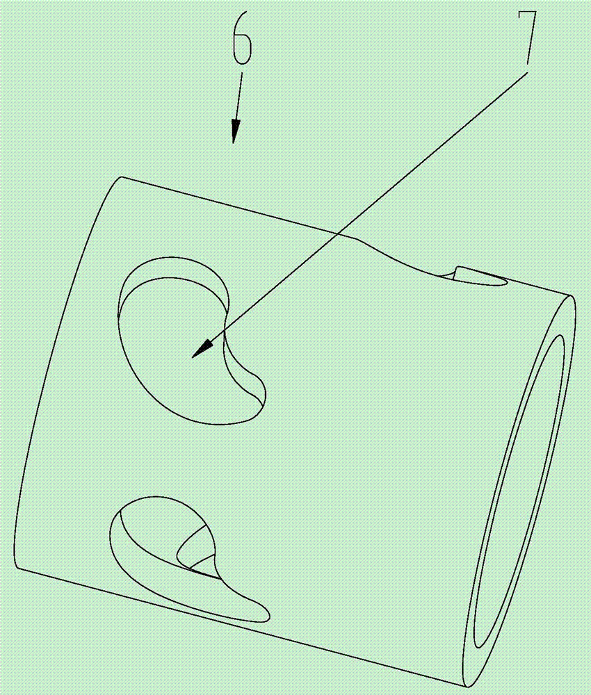
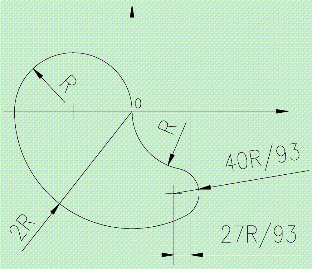
The invention discloses a feeding pipe barrel of a horizontal spiral discharge sedimentary centrifuge. The feeding pipe barrel comprises a barrel body. A plurality of discharge openings are formed in the barrel body and are in a streamline shape. All the discharge openings are distributed in a spiral mode. The invention further discloses the horizontal spiral discharge sedimentary centrifuge. The horizontal spiral discharge sedimentary centrifuge comprises a straight drum, a conical drum and a spiral body, wherein the conical drum is installed at one end of the straight drum, and the spiral body is arranged inside the conical drum. Spiral blades are arranged on the peripheral wall of the spiral body. A feeding pipe is arranged inside the spiral body. The feeding pipe barrel communicated with the feeding pipe is arranged inside the spiral body. The disturbance influence formed by fluid on a sedimentary separation area during suspension liquid discharging can be effectively reduced, and the centrifugal separation effect is improved.

Description

technical field [0001] The invention belongs to the technical field of centrifugation and separation equipment, and in particular relates to a horizontal spiral unloading sedimentation centrifuge and a feeding pipe cylinder. Background technique [0002] When the decanter centrifuge centrifuges the suspension, the material enters the feed tube cylinder from the feed pipe, and with the high-speed rotation of the drum, the suspension is centrifugally accelerated from the five outlets, and the material is discharged quickly. . At present, the shape of the discharge port of the feed tube body is designed to be a perfect circle, and the suspension is discharged straight from the perfect circular discharge port. Although it can meet the requirements of the discharge to a certain extent, it will cause problems. The discharge area in the liquid pool is undergoing the process of sedimentation and separation to form deflection, which causes different degrees of turbulent flow and aff...

Claims


Application Information

Patent Timeline
Patent Type & Authority Patents(China)
IPC IPC(8): B04B11/04
CPCB04B2001/2033
Inventor 杜洪刚周凌峰
Owner GREEN WATER SEPARATION EQUIP
Learn More