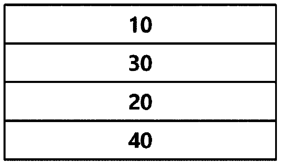
Optical laminate

An optical layer and combination technology, applied in optics, optical elements, filters, etc., can solve problems such as deterioration of the visual appreciation characteristics of polarizers

Active Publication Date: 2020-08-11
SHANJIN OPTOELECTRONICS SUZHOU CO LTD
View PDF10 Cites 0 Cited by
  • Summary
  • Abstract
  • Description
  • Claims
  • Application Information

AI Technical Summary

Problems solved by technology

However, since there is a problem that the visual appreciation characteristics of the polarizing plate deteriorate due to yellowing occurring in the pressure-sensitive adhesive layer depending on the type of the ultraviolet absorber, there is a need for a method that can minimize the deterioration of the visual appreciation characteristics of the polarizing plate. The composition of UV absorbers was studied

Method used


Image

  • Optical laminate
  • Optical laminate
  • Optical laminate

Examples


Embodiment Construction

[0176] Hereinafter, the present application is described with reference to examples. However, the scope of rights of the present application is not limited by the following examples.

[0177] 1. Evaluation of optical properties of polarizing plates

[0178] The polarizing plates prepared in Examples and Comparative Examples were cut into a size of 25 mm×25 mm (width×length) to produce samples.

[0179] The blocking performance against ultraviolet rays including a blue region was evaluated by measuring the transmittance of the polarizing plate using an ultraviolet-visible spectrometer (V-7100, JASCO). Here, when the total light incident amount is set to 100, the transmittance represents the amount of light transmitted through the polarizing plate as a ratio of %.

[0180] 2. Durability evaluation under reliability conditions

[0181] Specimens prepared by cutting the polarizing plates prepared in Examples and Comparative Examples into a size of 90 mm×170 mm (width×length) we...


PUM


Abstract

The present application relates to an optical laminate and a use thereof. The optical laminate of the present application is excellent in blocking ultraviolet rays, particularly ultraviolet rays including a blue light region of 380 nm or more. Especially when applied to an organic light emitting device, the optical laminate of the present application can minimize shortening of the lifetime of a blue light source in the organic light emitting device. The optical laminate of the present application has little change in color values and can exhibit excellent durability while not affecting opticalproperties. The optical laminate is particularly suitable when used in an organic light emitting device.

Description

technical field [0001] This application claims the benefit of the filing date of Korean Patent Application No. 10-2018-0152232 filed with the Korean Intellectual Property Office, the disclosure of which is incorporated herein by reference in its entirety. [0002] This application relates to optical laminates and uses thereof. Background technique [0003] In order to protect the polarizer, the polarizing plate can block ultraviolet rays by applying a protective film. On the other hand, as disclosed in Patent Document 1, the ultraviolet blocking function of a polarizing plate is mainly realized in a protective film for a polarizing plate. In addition, the protective film for polarizing plates is designed to block light having a wavelength of about 380 nm or less in order to protect the polarizer from ultraviolet rays. [0004] On the other hand, in OLED (Organic Light Emitting Diode), as a method of realizing RGB (red, green, blue) colors, a method of applying a color filt...

Claims


Application Information

Patent Timeline
IPC IPC(8): C09J7/20G02B5/20G02B1/04C09J11/06C09J133/00H01L51/50
CPCC09J7/20C09J11/06C09J133/00G02B1/04G02B5/20H10K50/10
Inventor 尹夏松柳英昌金美仙卢承周吴政宣孙贤喜徐光洙
Owner SHANJIN OPTOELECTRONICS SUZHOU CO LTD
Why Eureka
Try Eureka