
Processor verification method and device, electronic equipment and storage medium

A processor and technology to be verified, applied in the computer field, can solve problems such as missing scenarios, low efficiency, and inability to verify, and achieve the effect of ensuring correctness and integrity

Pending Publication Date: 2020-08-11
BEIJING BAIDU NETCOM SCI & TECH CO LTD
View PDF25 Cites 3 Cited by
  • Summary
  • Abstract
  • Description
  • Claims
  • Application Information

AI Technical Summary

Problems solved by technology

Using the above two verification platforms to verify the processor, the processor can only be verified through the directional test vectors of typical use cases or typical applications, which will make it impossible to verify for atypical use cases and atypical applications
Moreover, the FPGA platform cannot be completely consistent with the IC front-end verification platform. For example, clock reset strategy, memory and other standard cell timings, etc., their implementation on the FPGA platform cannot be completely consistent with their implementation on the ASIC platform; if only If one of the verification platforms is selected for verification, it will inevitably lead to the omission of some scenarios that can be verified by the other verification platform
In addition, the FPGA platform is very inefficient in the process of eliminating vulnerabilities. It is usually necessary to reproduce the problems found in the FPGA platform on the Register Transfer Level (RTL) verification platform, and then determine the vulnerabilities, which seriously reduces the design performance. Efficiency of iteration

Method used


Image

  • Processor verification method and device, electronic equipment and storage medium
  • Processor verification method and device, electronic equipment and storage medium
  • Processor verification method and device, electronic equipment and storage medium

Examples


Embodiment 1

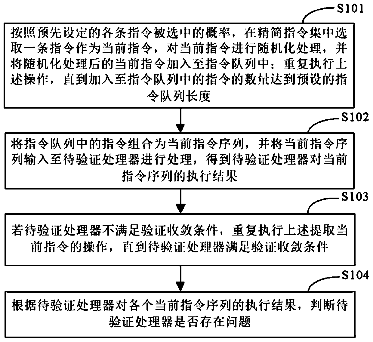
[0032] figure 1 It is a schematic flowchart of a method for verifying a processor provided in Embodiment 1 of the present application. The method can be executed by a device for verifying a processor, an electronic device, or a random instruction generation platform. The device, electronic device, or random instruction generation platform can be implemented by a software and / or hardware, the device or electronic device can be integrated into any smart device with network communication function. Such as figure 1 As shown, the method for authenticating a processor may include the following steps:

[0033] S101. According to the preset probability of each instruction being selected, select an instruction in the reduced instruction set as the current instruction, perform randomization processing on the current instruction, and add the randomized current instruction to the instruction queue; repeat The above operations are performed until the number of instructions added to the i...

Embodiment 2

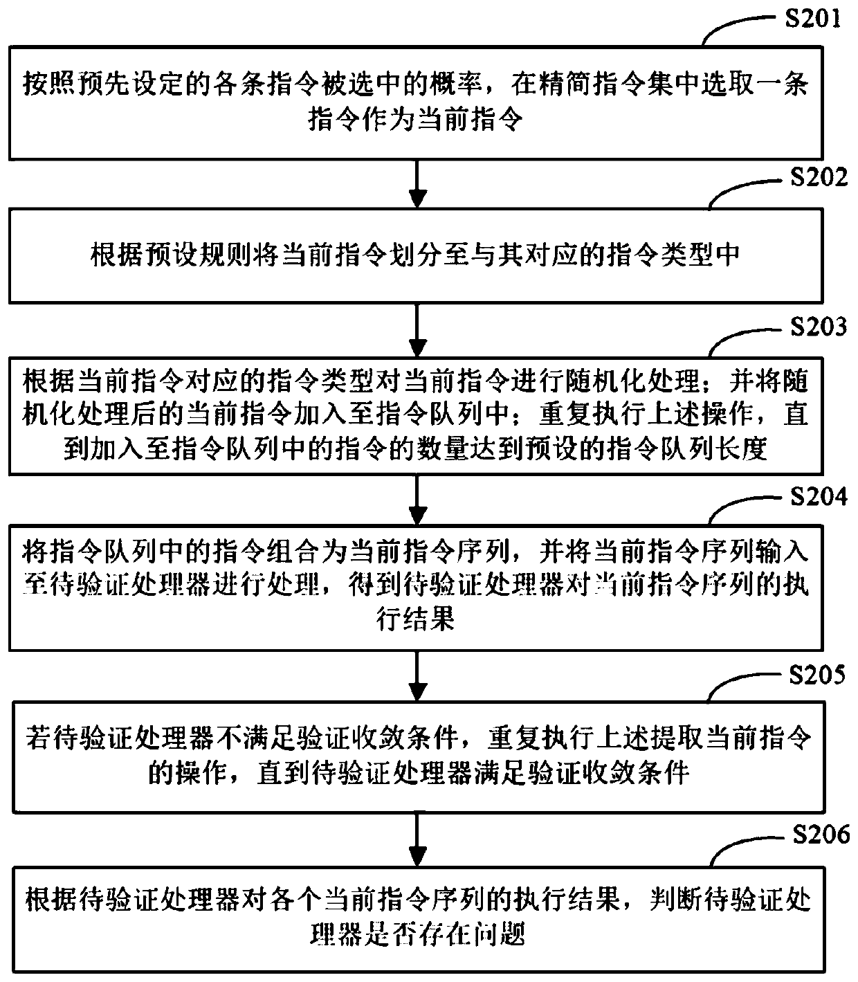
[0045] figure 2 It is a schematic flowchart of the method for verifying a processor provided in Embodiment 2 of the present application. Such as figure 2 As shown, the method for authenticating a processor may include the following steps:

[0046] S201. Select an instruction from the reduced instruction set as the current instruction according to the preset probability of each instruction being selected.

[0047] In a specific embodiment of the present application, the electronic device may select an instruction in the reduced instruction set as the current instruction according to a preset probability of each instruction being selected. Specifically, when selecting the current instruction for the first time, the electronic device can pre-set the probability of each instruction being selected as the same probability value. Therefore, when the electronic device selects the current instruction for the first time, it can follow the The probability of an instruction being sel...

Embodiment 3

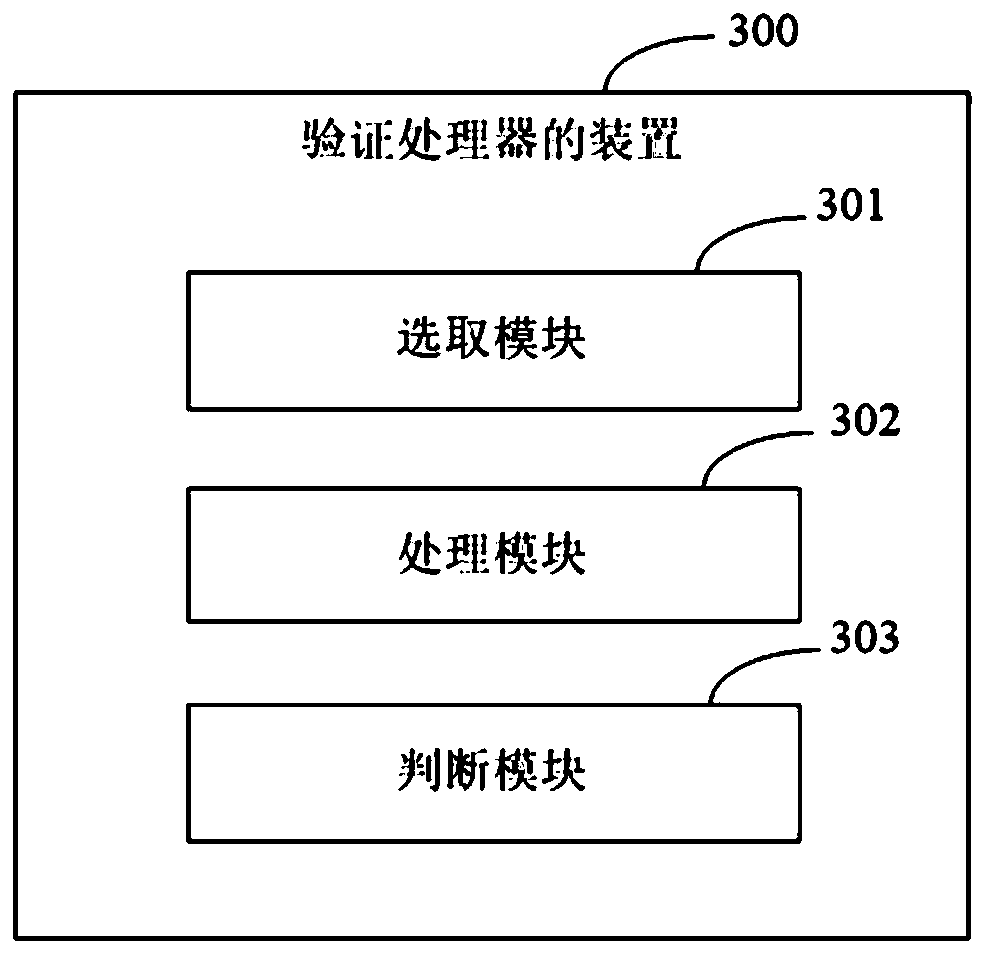
[0062] image 3 It is a schematic structural diagram of the verification processor device provided in Embodiment 3 of the present application. Such as image 3 As shown, the device 300 includes: a selection module 301, a processing module 302 and a judging module 303; wherein,

[0063] The selecting module 301 is configured to select an instruction in the reduced instruction set as the current instruction according to the preset probability of each instruction being selected, perform randomization processing on the current instruction, and add the randomized current instruction to into the instruction queue; repeat the above operations until the number of instructions added to the instruction queue reaches the preset length of the instruction queue;

[0064] The processing module 302 is configured to combine the instructions in the instruction queue into a current instruction sequence, and input the current instruction sequence to the processor to be verified for processing,...


PUM


Abstract

The invention discloses a processor verification method and device, electronic equipment and a storage medium, and relates to the technical field of integrated circuits. According to the specific scheme, one instruction is selected from a simplified instruction set to serve as a current instruction, randomization processing is conducted on the current instruction, and the processed current instruction is added into an instruction queue; repeatedly executing the operation until the number of the instructions added into the instruction queue reaches a preset instruction queue length; combining the instructions in the instruction queue into a current instruction sequence, and inputting the current instruction sequence into a to-be-verified processor for processing to obtain an execution result of the current instruction sequence; if the processor to be verified does not meet the verification convergence condition, repeatedly executing the operation until the processor to be verified meetsthe verification convergence condition; and judging whether the to-be-verified processor has a problem or not according to the execution result of each current instruction sequence. According to theembodiment of the invention, the processor can be verified for atypical cases and atypical applications, and the correctness and integrity of processor implementation are ensured.

Description

technical field [0001] The present application relates to the field of computer technology, and further relates to integrated circuit technology, especially a method, device, electronic equipment and storage medium for verifying a processor. Background technique [0002] The RISC-V instruction set is an open source instruction set. The processor implemented based on the RISC-V instruction set needs to fully execute various instructions defined in the RISC-V instruction set. During the verification process of the processor implemented based on the RISC-V instruction set In , it is very important to verify the correctness and integrity of the processor implementation to verify that the process and results of the processor's execution of instructions fully comply with the definition of the RISC-V instruction set. [0003] In the existing method for verifying a processor, the processor may be verified through an IC front-end verification platform or the processor may be verified...

Claims


Application Information

Patent Timeline
IPC IPC(8): G06F30/34G06F9/30
CPCG06F30/34G06F9/30145Y02D10/00
Inventor 李炎
Owner BEIJING BAIDU NETCOM SCI & TECH CO LTD
Learn More