Multifunctional cleaning bionic robotic fish for industrial aquaculture area

A technology for robotic fish and breeding areas, which is applied in fish farming, agricultural fishing, climate change adaptation, etc. It can solve the problems of high voltage safety, single function, and large energy consumption, and achieve low instrument cost and environmental protection. Good compatibility and enhanced battery life

Pending Publication Date: 2020-08-11
SHANGHAI OCEAN UNIV
View PDF2 Cites 2 Cited by
  • Summary
  • Abstract
  • Description
  • Claims
  • Application Information

AI Technical Summary

Problems solved by technology

[0008] (1) oversized
For some small-scale farming areas or dead corners of farming areas, it is difficult for the above-mentioned bionic robot fish to monitor changes in water blooms;
[0009] (2) Single function
The functions of the above-mentioned robotic fish tend to be simplified, and only carry the function of water quality monitoring;
[0010] (3) Difficult to predict the outbreak of algal blooms
The above-mentioned robotic fish uses carbon fiber as the shell material. The flexibility and control performance of the robotic fish are relatively poor, and it is easy to disturb the fish. It lacks the consideration of environmental compatibility;
[0012] (5) Higher cost
The above-mentioned robotic fish is made of aluminum composite material, and the cost is relatively high;
[0013] (6) poor security
The high voltage generated during the use of the three-phase asynchronous motor for the above-mentioned robotic fish is not safe, and it is easy to cause electric leakage accidents, resulting in the death of fish schools by electric shock
The aforementioned robotic fish uses a laser sensor, and the laser emitted by the sensor is harmful to fish schools;
[0014] (7) Poor energy saving
The use of three-phase asynchronous motors for the aforementioned robotic fish consumes a large amount of energy

Method used


Image

  • Multifunctional cleaning bionic robotic fish for industrial aquaculture area
  • Multifunctional cleaning bionic robotic fish for industrial aquaculture area
  • Multifunctional cleaning bionic robotic fish for industrial aquaculture area

Examples


Embodiment Construction

[0045] The embodiments of the present invention are described in detail below in conjunction with the accompanying drawings: this embodiment is implemented on the premise of the technical solution of the present invention, and detailed implementation methods and specific operating procedures are provided, but the protection scope of the present invention is not limited to the following the described embodiment.

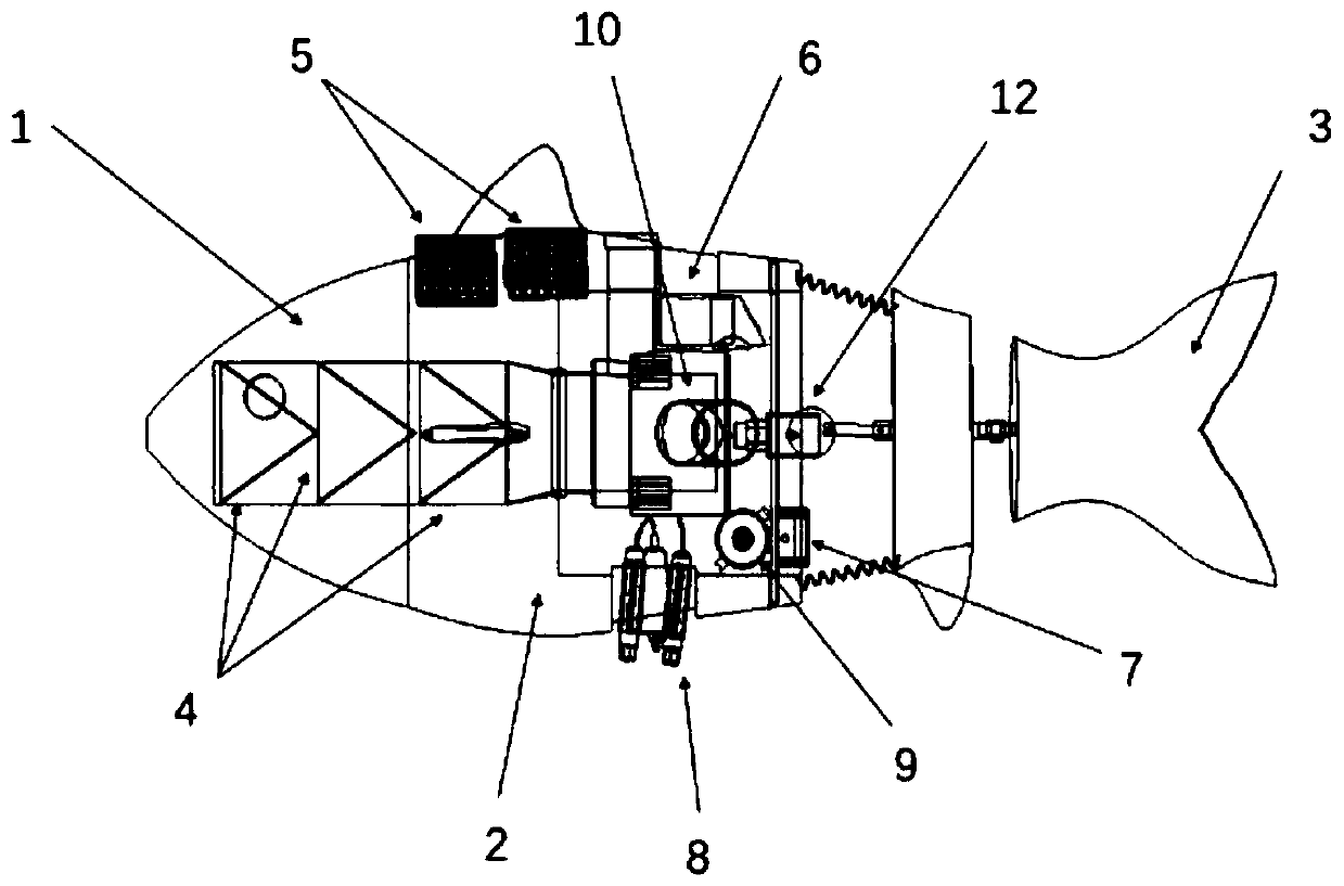
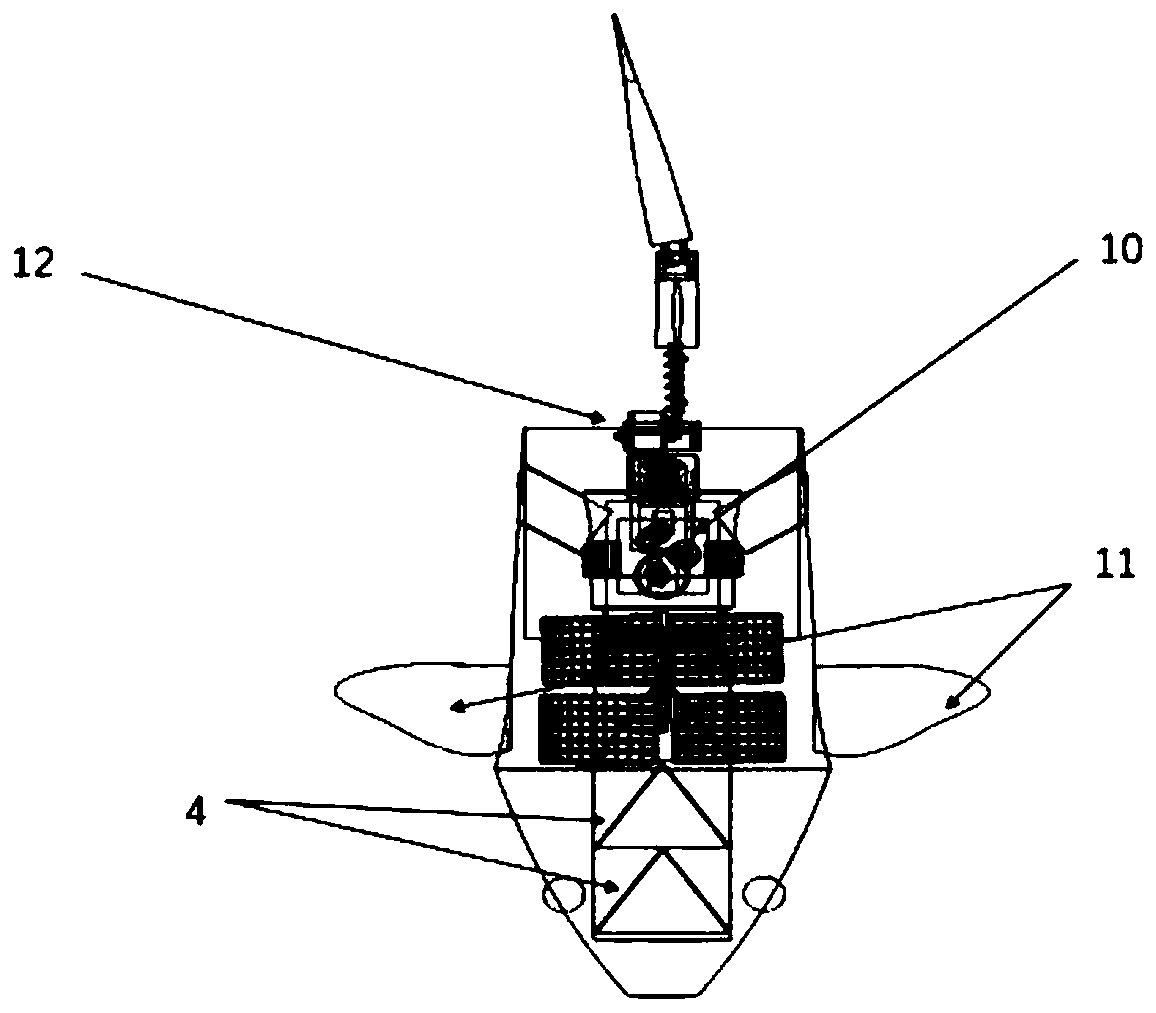
[0046] Such as Figure 1-Figure 5 As shown, it includes a fish head 1, a fish body 2, and a fish tail 3. The fish head 1 includes a joint from the fish mouth to the front end of the fish body front, and the fish body 2 is divided into a fish body front, a fish body The middle part of the body and the rear part of the fish include the junction from the end of the fish head 1 to the front end of the fish tail 3. The fish tail is from the end of the rear part of the fish to the end of the fish tail. The fish body 2 and the fish head 1 are respectively hollow shells Body...


PUM

PropertyMeasurementUnit
densityaaaaaaaaaa
elastic modulusaaaaaaaaaa
pore sizeaaaaaaaaaa

Abstract

The invention discloses a multifunctional cleaning bionic robotic fish for an industrial aquaculture area. The multifunctional cleaning bionic robotic fish comprises a fish head, a fish body and a fish tail which are connected in sequence; the fish body and the fish head are of a hollow shell structure, the hollow shell is made of an anticorrosion material, the surface of the shell is covered withan anticorrosion soft material to serve as an outer skin, and a plankton net, a water pump, an information collector assembly, a watertight compartment, an ultrasonic device, an automatic bait casting machine, a flexible solar panel and the like are arranged in the hollow shell of the robotic fish body and at the proper positions of a fish body respectively; a power supply device, a microcontroller and a driving control module are arranged in the watertight compartment; a tail fin driving device is arranged at the tail of the robotic fish body, and a left pectoral fin driving device and a right pectoral fin driving device are arranged on the fish body; and the power supply device and the microcontroller supply power to each power supply object and control the power supply objects. The multifunctional cleaning bionic robotic fish for the industrial aquaculture area is safe, reliable, low in cost, easy to popularize and capable of predicting water bloom outbreak.

Description

technical field [0001] The patent of the present invention relates to the technical field of water bloom treatment in aquaculture area, in particular to a multifunctional cleaning bionic robot fish in industrial aquaculture area that uses physical methods to clean water blooms. Background technique [0002] In recent years, with the increasingly serious water pollution and eutrophication in aquaculture areas, large-scale algal blooms often occur. However, due to the lack of prevention in many breeding areas or the inconvenient installation and imperfect functions of large-scale algae removal machines, and the use of chemical algae removal reagents that lead to secondary pollution of the water body, the breeding objects died, and more seriously caused the ecological system imbalance in the breeding area, reducing the Economic and ecological benefits of breeding areas. The loss caused by this situation can be avoided by designing and developing a new type of algae removal mac...

Claims


Application Information

Patent Timeline
Patent Type & Authority Applications(China)
IPC IPC(8): B63H1/36B63C11/52A01K61/80C02F1/36G01N33/18
CPCA01K61/80B63C11/52B63H1/36C02F1/36G01N33/18Y02P60/60Y02A40/81
Inventor 孔祥洪刘必林陈新军郑芯瑜
Owner SHANGHAI OCEAN UNIV
Why Eureka
Try Eureka