
Differential capacitance detection circuit based on sampling holder demodulation

A sample-and-hold, differential capacitor technology, applied in capacitance measurement, measurement of resistance/reactance/impedance, and transmission of sensing components using electromagnetic/magnetic devices, etc., can solve the problems of amplified amplitude gain loss, etc. Conducive to miniaturization and the effect of saving operational amplifiers

Inactive Publication Date: 2020-08-07
ZHEJIANG UNIV
View PDF4 Cites 4 Cited by
  • Summary
  • Abstract
  • Description
  • Claims
  • Application Information

AI Technical Summary

Problems solved by technology

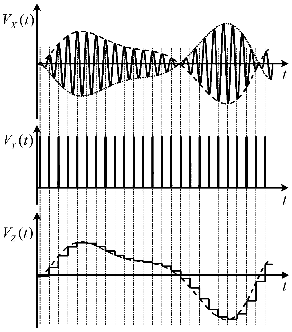
[0004] In this traditional modulation and demodulation capacitance detection circuit, the envelope of the phase-sensitive demodulation output signal is the capacitance change signal, but it contains rich high-frequency carrier information, so the effective value is only 0.707 times the peak value, that is, the modulation process The amplitude gain of medium amplification has a certain loss in the demodulation process

Method used


Image

  • Differential capacitance detection circuit based on sampling holder demodulation
  • Differential capacitance detection circuit based on sampling holder demodulation
  • Differential capacitance detection circuit based on sampling holder demodulation

Examples


Embodiment Construction

[0013] specific implementation plan

[0014] In order to make the purpose, technical solutions and advantages of the embodiments of the present invention more clear, the technical solutions in the embodiments of the present invention will be clearly and completely described below in conjunction with the drawings in the embodiments of the present invention. Apparently, the above-described embodiments are some, but not all, embodiments of the present invention. Based on the embodiments of the present invention, other embodiments obtained by persons of ordinary skill in the art without making creative efforts all belong to the protection scope of the present invention.

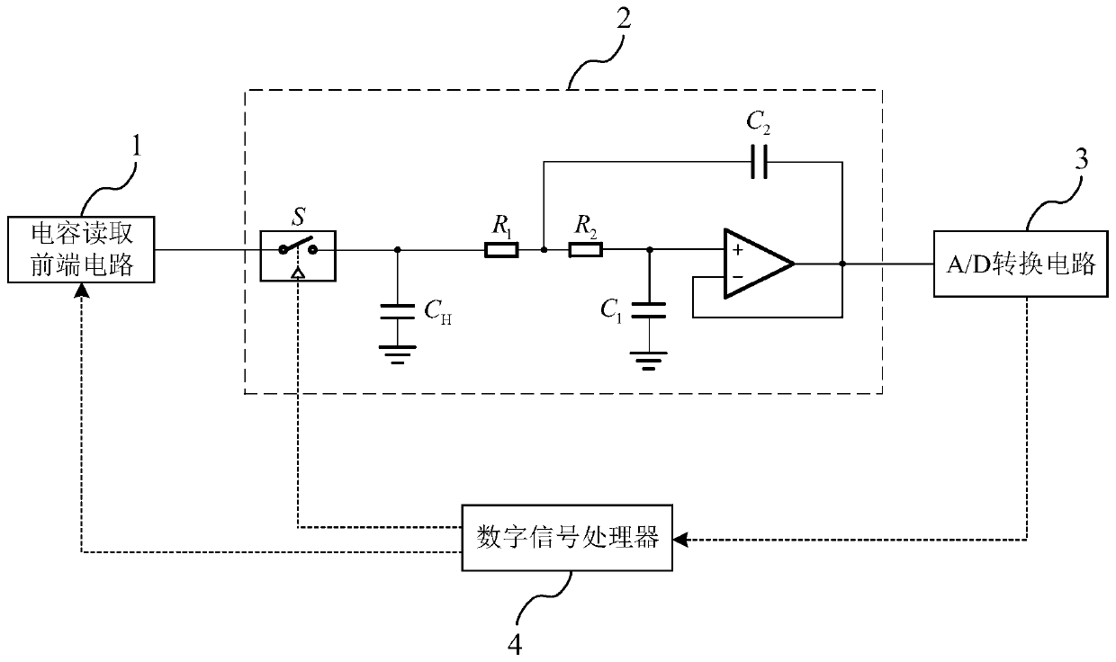
[0015] A differential capacitance detection circuit based on sample-and-hold demodulation of the present invention detects the variation of a pair of differential capacitances through a modulation and demodulation method, and the phase-sensitive demodulation circuit adopts a sample-and-hold to lock the modulated ...


PUM


Abstract

The invention discloses a differential capacitance detection circuit based on sampling holder demodulation. The circuit comprises a capacitance reading front-end circuit, a demodulation and low-pass filter circuit, an A / D conversion circuit and a digital signal processor 4 used for controlling the carrier frequency and analog switch driving signals. According to the demodulation and low-pass filtering circuit, a sampling holder is adopted as a phase-sensitive demodulation scheme, so that an effective value of a demodulation output signal is close to the amplitude of an envelope, the high-frequency carrier waves are effectively suppressed while demodulation is performed, and the capacitance detection noise is reduced. Under the same capacitance detection gain, the power supply voltage of the device is reduced, so that the static power consumption of a chip is reduced; a buffer amplifier demodulation circuit of the sampling holder is combined with a post-stage low-pass filter, so that anoperational amplifier is saved, the structure is simple, and the product design of the miniaturization of the sensor is facilitated.

Description

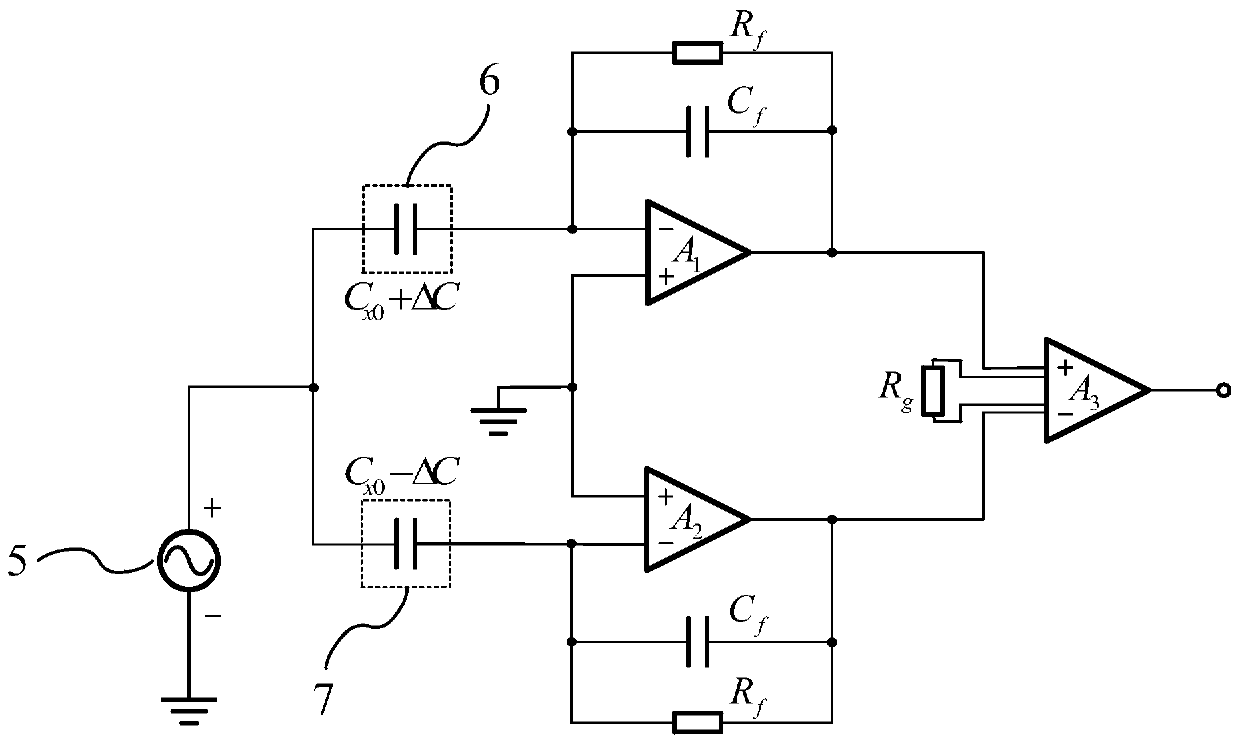
technical field [0001] The invention relates to the technical field of capacitance detection, in particular to a differential capacitance detection circuit based on sample-and-hold demodulation. Background technique [0002] At present, in high-precision sensors whose changes in physical quantities such as displacement sensors, acceleration sensors, and gyroscopes can cause changes in sensitive capacitance, various signal conditioning circuits can be used to convert weak capacitance signals into voltages, currents, or frequencies that are convenient for measurement and transmission. Therefore, there are requirements for low noise, low power consumption, and simple structure for the capacitance detection circuit. [0003] It is known that there is a traditional modulation and demodulation capacitance detection scheme for differential capacitance sensors, which is as follows: firstly, through the modulation circuit, the capacitance change to be measured is converted into the v...

Claims


Application Information

Patent Timeline
IPC IPC(8): G01R27/26G01D5/24
CPCG01D5/24G01R27/2605
Inventor 黄添添金言叶凌云宋开臣
Owner ZHEJIANG UNIV
Learn More