
Operational transconductance amplifier, reconfigurable fully differential voltage sensing amplifier and reconfigurable fully differential capacitive sensing amplifier

a operational transconductance technology, which is applied in differential amplifiers, amplifiers with semiconductor devices/discharge tubes, amplifier details, etc., can solve the problems of unsatisfactory power consumption and noise generated in conventional amplifying circuits, and achieve precise bias driving circuits, the performance of fully differential voltage sensing amplifiers and fully differential capacitive sensing amplifiers implemented by utilizing the disclosed operational transconductance amplifiers is improved, and the power consumption

Active Publication Date: 2015-07-16
NAT TAIWAN UNIV OF SCI & TECH
View PDF4 Cites 20 Cited by
  • Summary
  • Abstract
  • Description
  • Claims
  • Application Information

AI Technical Summary

Benefits of technology

This patent is about a new design for voltage sensing amplifiers that allows them to be programmed and reconfigured for different applications. By using a bias driving circuit and a common mode feedback circuit, the amplifiers consume less power and provide a more precise bias driving circuit, resulting in improved performance. The amplifiers can also be adjusted to have different bandwidths and gains, and provide a high-pass frequency response to filter out low-frequency interference and noise. The noise efficiency factor of the amplifiers is improved compared to conventional amplifiers. Overall, this patent provides a reconfigurable low-power low-noise fully differential voltage sensing amplifier.

Problems solved by technology

Moreover, amplifying circuits in portable or injectable biomedical sensing devices also have to meet requirement for low-power consumption.
However, the power consumption and the noise generated in conventional amplifying circuits are not satisfactory when the conventional amplifying circuits are applied in the abovementioned applications.

Method used


Image

  • Operational transconductance amplifier, reconfigurable fully differential voltage sensing amplifier and reconfigurable fully differential capacitive sensing amplifier
  • Operational transconductance amplifier, reconfigurable fully differential voltage sensing amplifier and reconfigurable fully differential capacitive sensing amplifier
  • Operational transconductance amplifier, reconfigurable fully differential voltage sensing amplifier and reconfigurable fully differential capacitive sensing amplifier

Examples


Embodiment Construction

[0026]Reference will now be made in detail to the present embodiments of the disclosure, examples of which are illustrated in the accompanying drawings. Wherever possible, the same reference numbers are used in the drawings and the description to refer to the same or like parts.

[0027]Unless otherwise defined, all terms (including technical and scientific terms) used herein have the same meaning as commonly understood by one of ordinary skill in the art to which example embodiments belong. It will be further understood that terms, such as those defined in commonly used dictionaries, should be interpreted as having a meaning that is consistent with their meaning in the context of the relevant art and will not be interpreted in an idealized or overly formal sense unless expressly so defined herein.

[0028]In the following description and claims, the terms “coupled” and “connected”, along with their derivatives, may be used. In particular embodiments, “connected” and “coupled” may be used...


PUM


Abstract

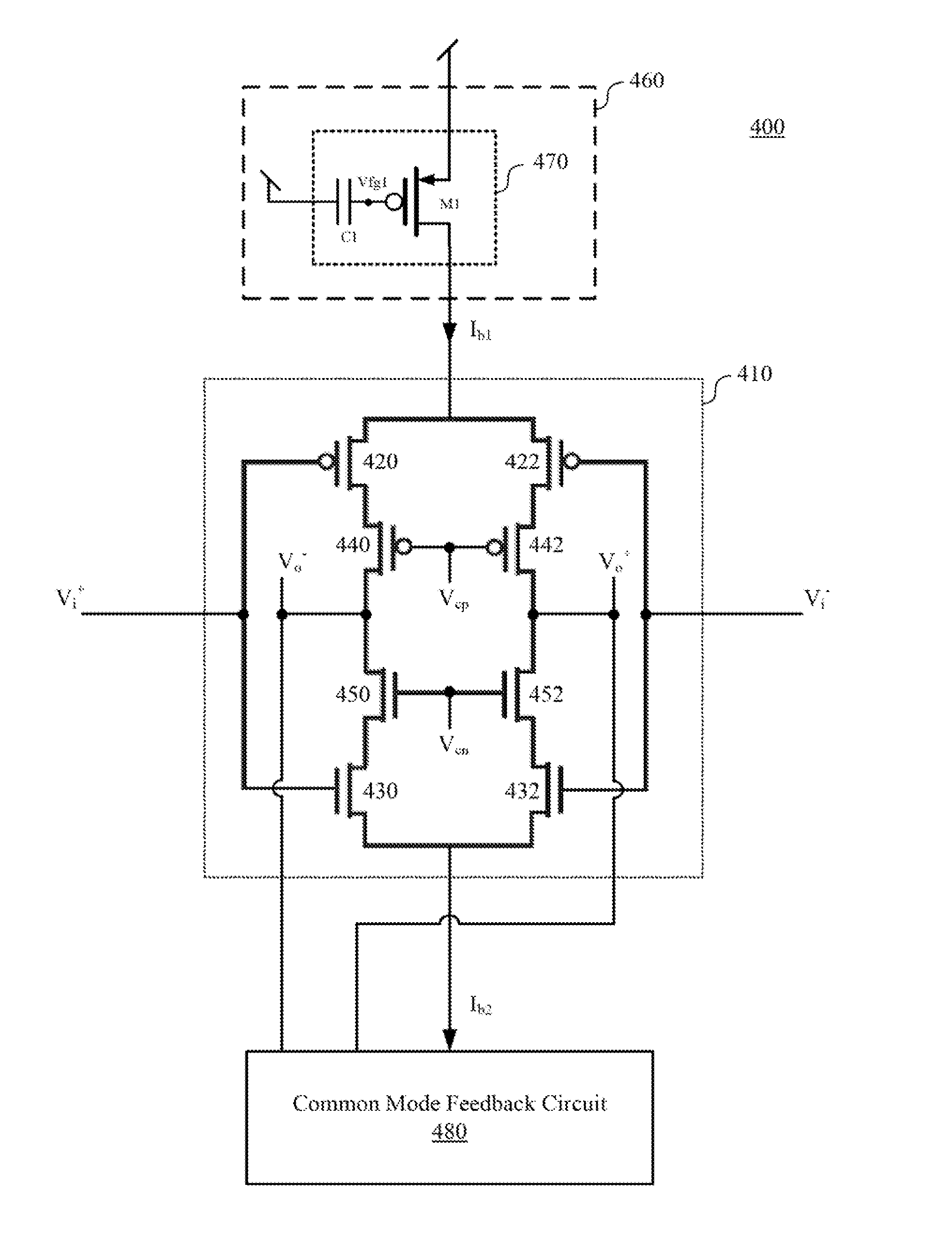
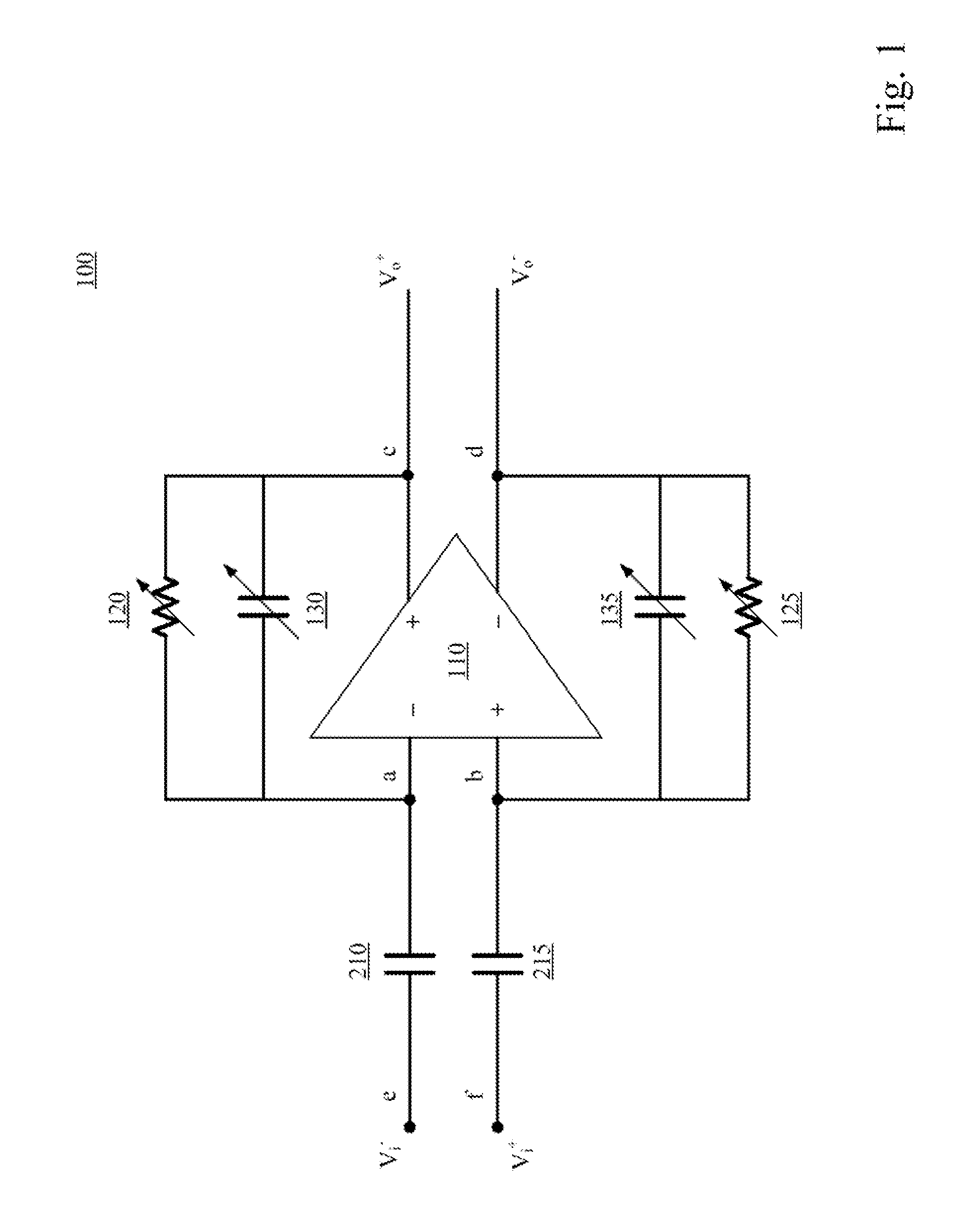
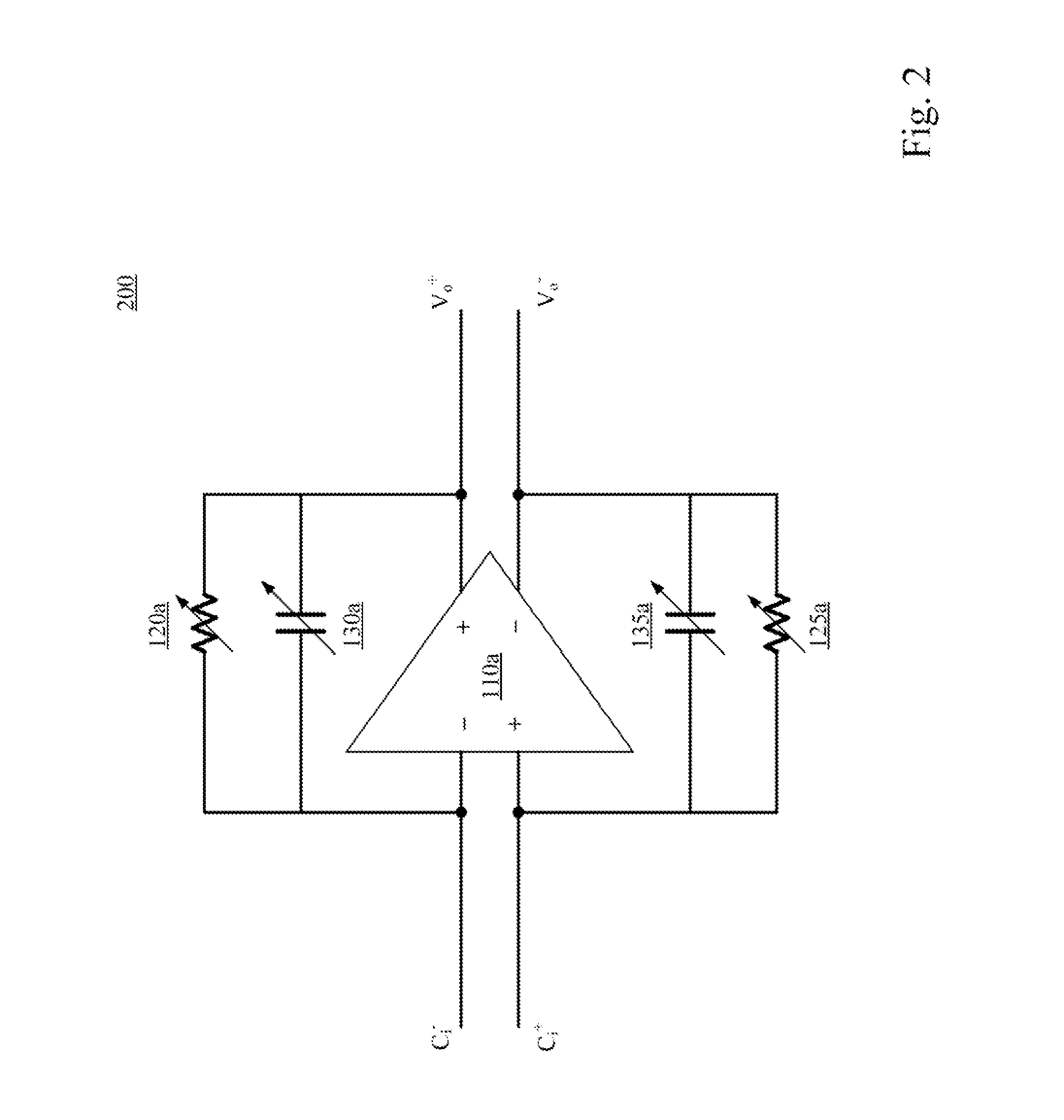
An operational transconductance amplifier includes a cascode differential-pair amplifying circuit, a bias driving circuit, and a common mode feedback circuit. The cascode differential-pair amplifying circuit is configured for receiving a differential input voltage and for providing a differential output voltage. The bias driving circuit is configured for providing a first bias current to drive the cascode differential-pair amplifying circuit and for adjusting the transconductance of the transconductance amplifier. The bias driving circuit includes a first floating-gate transistor. The first floating-gate transistor is configured for adjusting the first bias current. The common mode feedback circuit is configured for adjusting a second bias current of the cascode differential-pair amplifying circuit according to the differential output voltage so that the differential output voltage is stabilized. A reconfigurable fully differential voltage sensing amplifier and a reconfigurable fully differential capacitive sensing amplifier are disclosed herein as well.

Description

RELATED APPLICATIONS[0001]This application claims priority to Taiwan Application Serial Number 103101645, filed Jan. 16, 2014, the entirety of which is herein incorporated by reference.BACKGROUND[0002]1. Technical Field[0003]The present disclosure relates to a reconfigurable fully differential amplifier. More particularly, the present disclosure relates to an operational transconductance amplifier of the reconfigurable fully differential amplifier.[0004]2. Description of Related Art[0005]As the development of the applications of sensing devices, the demands for low-power, low-noise amplifying circuits are increasing nowadays. For example, low-noise amplifying circuits are required in biomedical sensing devices or environmental sensing devices such that the weak signals detected from creatures or natural environments can be amplified. Moreover, amplifying circuits in portable or injectable biomedical sensing devices also have to meet requirement for low-power consumption.[0006]Howeve...

Claims


Application Information

Patent Timeline
Patent Type & Authority Applications(United States)
IPC IPC(8): H03F3/45
CPCH03F3/45636H03F2203/45154H03F2203/45082H03F2203/45052H03F1/223H03F3/45188H03F3/45475H03F3/4565H03F2203/45292H03F2203/45311H03F2203/45352H03F2203/45404H03F2203/45512H03F2203/45522H03F2203/45528H03F2203/45544H03F2203/45631H03F3/45228H03F1/0272H03F3/45242H03F3/45H03F3/45479
Inventor WANG, TZU-YUNLAI, MIN-RUIPENG, SHENG-YU
Owner NAT TAIWAN UNIV OF SCI & TECH
Learn More