Fabricated box girder bridge and anti-seismic structure thereof

An anti-seismic structure and prefabricated technology, applied in the direction of bridges, bridge parts, bridge materials, etc., can solve the design method of reinforced concrete lateral limit stoppers, the detailed structure and its performance objectives, clearly stipulate, ignore the design of stoppers, and cannot Give full play to the block function and other issues to achieve the effect of ensuring the shear damage resistance, improving the shear resistance, and improving the shear damage resistance

Active Publication Date: 2020-08-07
CHANGAN UNIV
View PDF17 Cites 0 Cited by
  • Summary
  • Abstract
  • Description
  • Claims
  • Application Information

AI Technical Summary

Problems solved by technology

Among the current seismic codes for bridges, important codes such as "Detailed Rules for Seismic Design of Highway Bridges", "Code for Design of Highway Reinforced Concrete and Prestressed Concrete Bridges and Culverts", "Code for Seismic Resistance of Highway Engineering" and other important codes do not have detailed specifications for reinforced concrete transverse limit stops. The design method, detailed structure and performance goals are clearly stipulated, and it is only used as a structural measure, which leads to bridge engineering personnel ignoring the design of the stopper and failing to give full play to the role of the stopper

Method used


Image

  • Fabricated box girder bridge and anti-seismic structure thereof
  • Fabricated box girder bridge and anti-seismic structure thereof
  • Fabricated box girder bridge and anti-seismic structure thereof

Examples


Embodiment

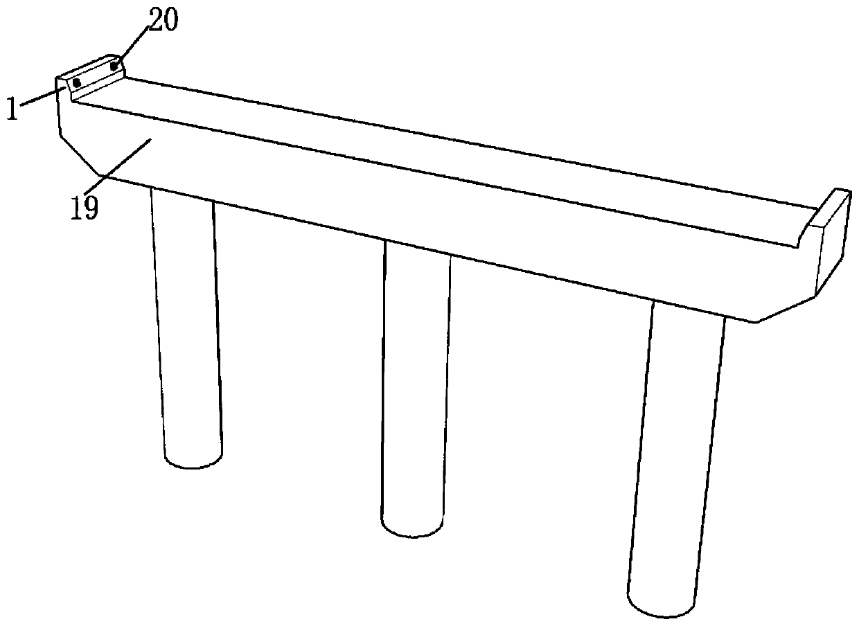
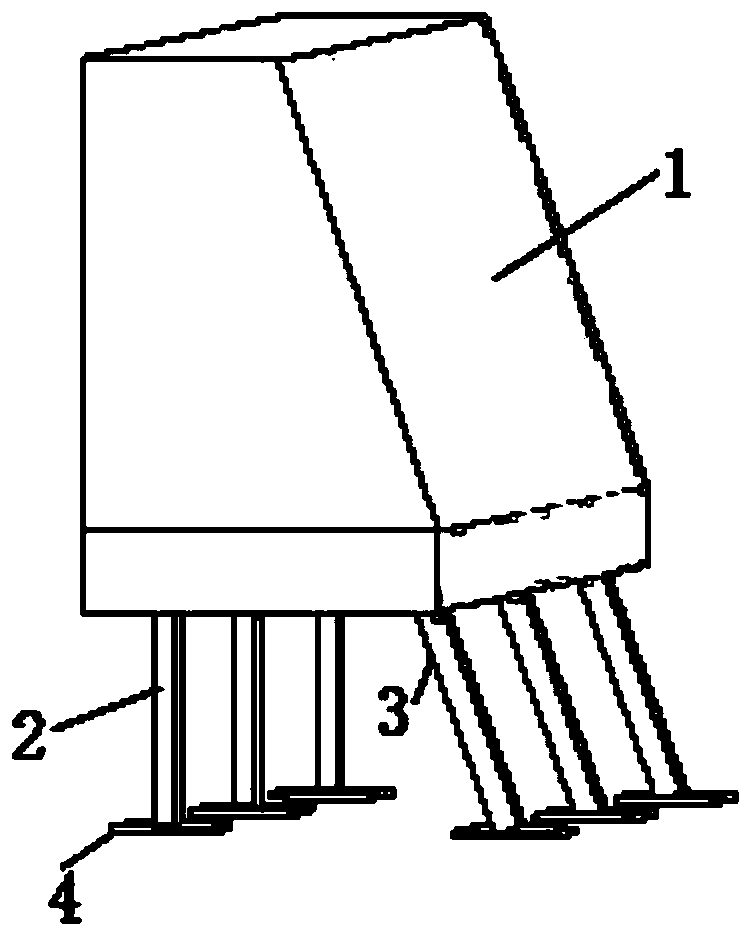
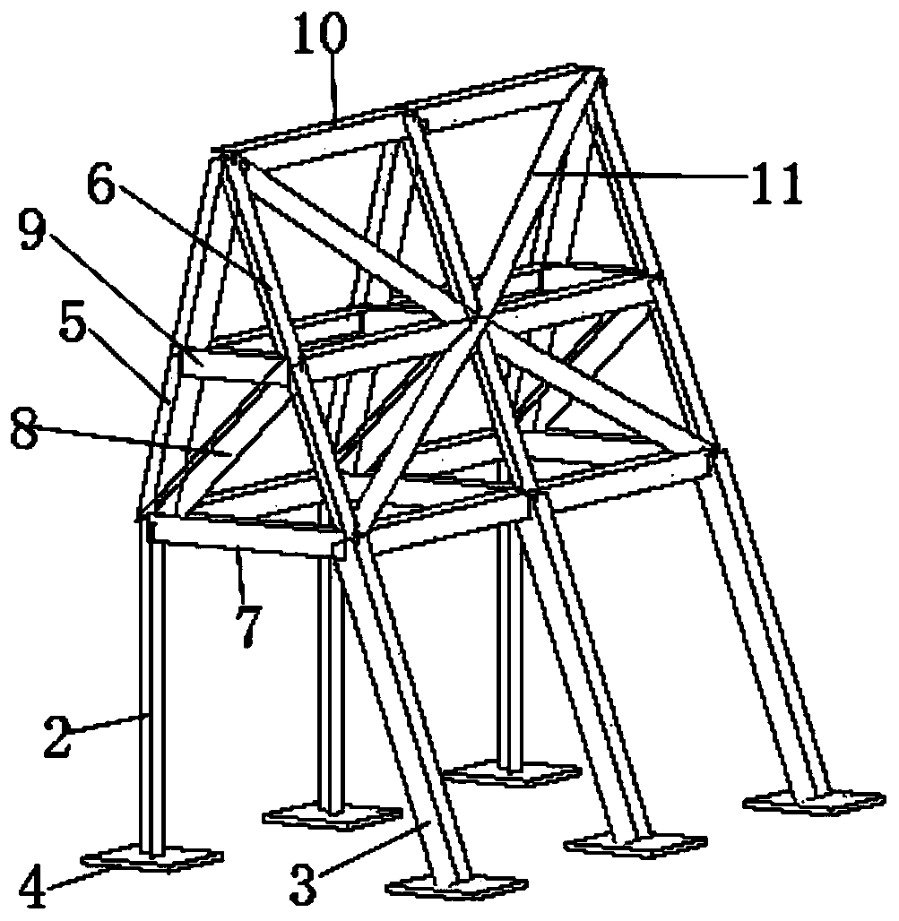
[0048] The anti-seismic structure of the assembled box girder bridge of the embodiment of the present invention includes a block 1, a vertical bar 2, a diagonal bar 3, a foot 4, a skeleton pressure bar 5, a skeleton tie rod 6, a skeleton large beam 7, a skeleton brace 8, and a small skeleton Crossbeam 9, framework longitudinal beam 10he framework vertical diagonal brace 11. See details Figure 1 to Figure 5 as well as Figure 6(a) ~ Figure 6(c) . Such as figure 1 As shown, the block 1 is located on both sides of the cover beam 19 , and the outer edge of the block 1 is flush with the edges at both ends of the cover beam 19 . A rubber pad 20 of 200×200×20 mm is pasted on the block 1, and two rubber pads 20 are arranged on one side of one block. Such as Figure 3 ~ Figure 5 as well as Figure 6(a) ~ Figure 6(c) As shown, the vertical bar 2, the oblique bar 3, the feet 4, the skeleton pressure bar 5, the skeleton tie rod 6, the skeleton large beam 7, the skeleton diagonal br...


PUM


Abstract

The invention discloses a fabricated box girder bridge and an anti-seismic structure thereof. The anti-seismic structure comprises check blocks located on the two sides of the cover beam, each steel framework piece is formed by welding a vertical rod, an inclined rod, a framework pressing rod, a framework pull rod, a framework large cross beam, a framework inclined strut and a framework small cross beam, and each steel framework is formed by welding a plurality of steel framework pieces arranged side by side through framework longitudinal beams and framework longitudinal inclined struts. According to the structure of the steel framework piece and the steel framework, it is guaranteed that the side, facing the interior of the bent cap, of the check block can bear large tensile force and theside, facing the exterior of the bent cap, of the check block can bear large pressure, and therefore the shear failure resistance of the oblique section, facing the bent cap, of the check block is improved; the steel skeleton pieces arranged side by side of the steel skeleton are connected through the skeleton longitudinal beams and the skeleton longitudinal inclined struts, so that the steel skeleton pieces are reliable in connection and high in impact resistance, the overall shear failure resistance of the check block is guaranteed, and the shock resistance of a bridge can be improved.

Description

technical field [0001] The invention relates to the field of bridge engineering, in particular to an assembled box girder bridge and its anti-seismic structure. Background technique [0002] Bridge limit stops refer to the block walls set on both sides of the bridge deck to prevent falling beams. For places where the earthquake is more serious, stoppers are also set between the beams to block the beams to prevent lateral movement. For trapezoidal and rectangular sections, it depends on the beam section. Reinforced concrete retaining blocks are widely used in domestic girder bridges, but the industry currently only regards retaining blocks as structural measures and does not participate in force analysis, and there are no clear regulations on the form and size of retaining blocks. At present, there are only principled regulations in highway seismic codes: in areas where the seismic fortification intensity is greater than or equal to 7 degrees, "for simply supported beam (sl...

Claims


Application Information

Patent Timeline
Patent Type & Authority Applications(China)
IPC IPC(8): E01D19/02E01D2/04E01D101/26E01D101/30
CPCE01D2/04E01D19/02E01D2101/26E01D2101/268
Inventor 王业路周勇军赵煜沈传东孙楠楠周先功
Owner CHANGAN UNIV
Why Eureka
Try Eureka