Steel surface polishing processing equipment

A technology for surface polishing and processing equipment, applied in metal processing equipment, grinding/polishing equipment, surface polishing machine tools, etc., can solve the problems of reducing the flatness of stainless steel, flying cheap, affecting the smoothness of stainless steel, etc. Effect

Inactive Publication Date: 2020-08-07
曹兵
View PDF0 Cites 1 Cited by
  • Summary
  • Abstract
  • Description
  • Claims
  • Application Information

AI Technical Summary

Problems solved by technology

[0002] The polishing processing equipment uses the friction generated by the rotation to polish the steel surface to reduce the surface roughness of the steel to obtain smooth and flat steel. When using nylon wheels to polish stainless steel, due to the oxide layer on the surface of the stainless steel, the polished oxide layer will fly. Irregular-shaped grinding debris will fly to the surface of the stainless steel that is about to be polished, so that the nylon wheel will polish the grinding debris, causing some grinding debris to re-attach to the stainless steel, and because the shape of the thrown grinding debris is not Rules, plaques will be formed after bonding, resulting in the need for multiple polishing, affecting the smoothness of stainless steel and reducing the flatness of stainless steel

Method used


Image

  • Steel surface polishing processing equipment
  • Steel surface polishing processing equipment
  • Steel surface polishing processing equipment

Examples


Embodiment 1

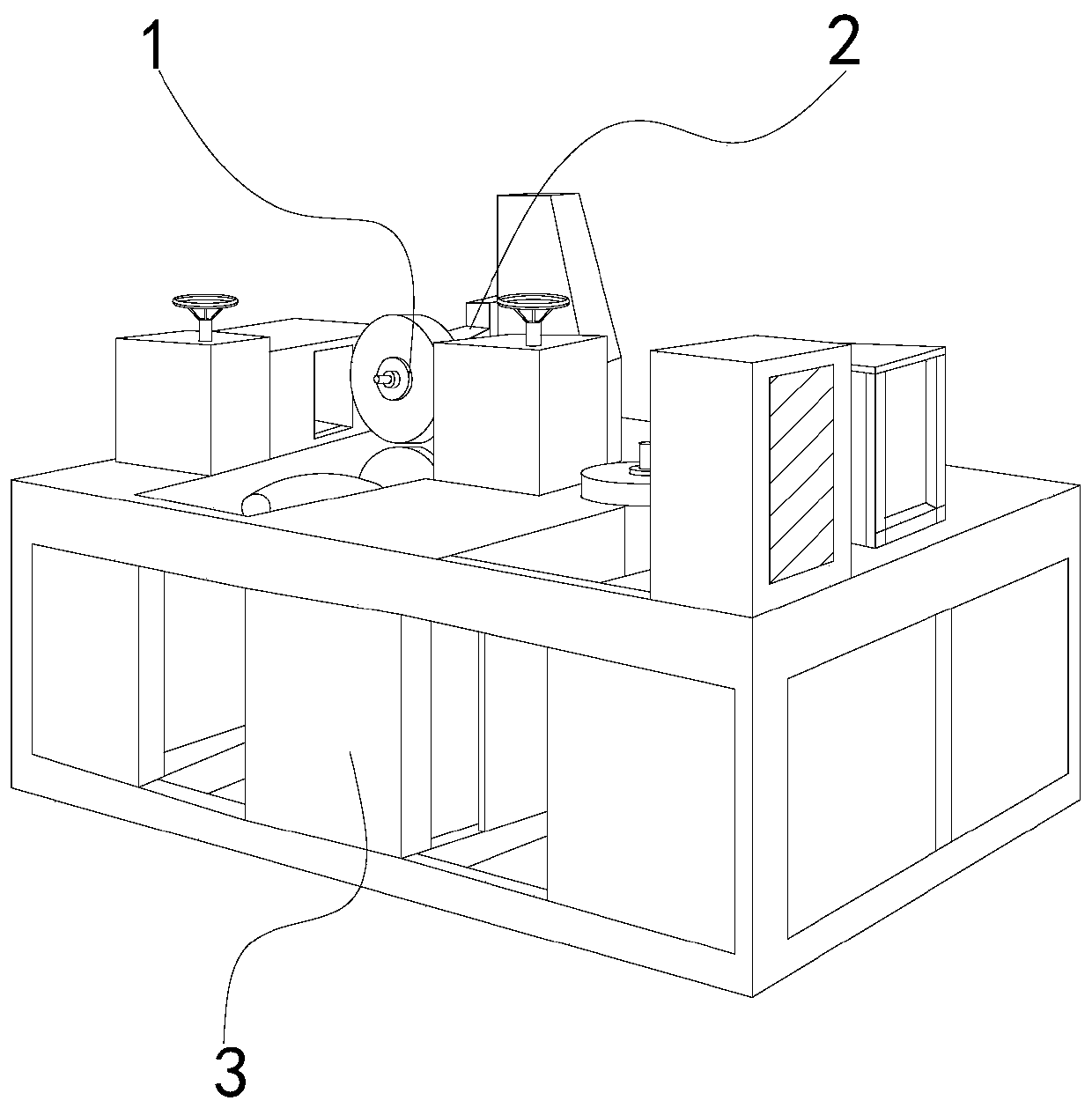
[0025] Such as Figure 1-Figure 4 Shown:

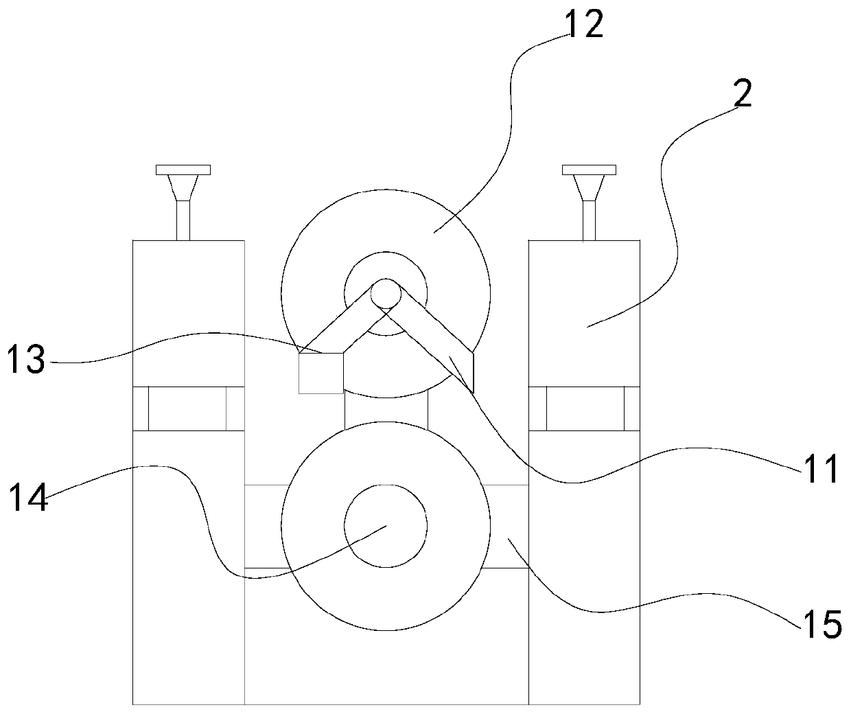
[0026] The present invention is an equipment for steel surface polishing. Its structure includes a polishing device 1, an adjuster 2, and a bracket 3. The adjuster 2 is installed on both sides of the polishing device 1, and the polishing device 1 is embedded in the bracket 3. The upper end of the adjuster 2 is welded on the upper surface of the bracket 3. The polishing device 1 is composed of a cleaning device 11, a polishing wheel 12, a sweeper 13, a sliding shaft 14, and a fixed plate 15. The cleaning device 11 is located in the polishing On both sides of the wheel 12, the upper end of the sweeper 13 and the upper end of the cleaning device 11 are located on the same central axis, the sliding shaft 14 is installed in the middle of the fixed plate 15, and the sweeper 13 is located on the left side of the polishing wheel 12. The fixed plate 15 is embedded in the lower inner side of the adjuster 2, the lower end of the cleaning device...

Embodiment 2

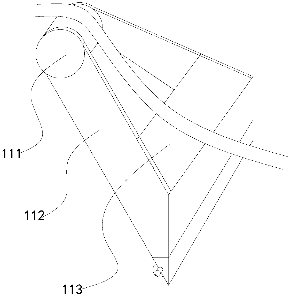
[0032] Such as Figure 5-Figure 8 Shown:

[0033] Wherein, the sweeper 13 is provided with a curved plate 131, a sweeping mechanism 132, a triangular block 133, an embedded plate 134, and a supporting plate 135, and the two ends of the curved plate 131 are welded on the inner side of the supporting plate 135, and the embedded The plate 134 is embedded in the lower end of the support plate 135, the cleaning mechanism 132 is embedded in the inner side of the embedded plate 134, the triangular block 133 is attached to the left lower end of the embedded plate 134, and the inner side of the support plate 135 Embedded on the outside of the polishing wheel 12, the curved plate 131 is a smooth surface structure, and the lower end is matched with the internal clearance of the sweeping mechanism 132, so that the cleaned abrasive debris can slide from the curved plate 131 to the surface of the sweeping mechanism 132 to avoid abrasive debris Accumulated inside the lower end of the sweepi...


PUM


Abstract

The invention discloses steel surface polishing processing equipment. The steel surface polishing processing equipment structurally comprises a polishing device, an adjuster and a bracket, wherein thepolishing device consists of cleaning devices, a polishing wheel, a sweeper, a sliding shaft and a fixed plate, stainless steel penetrates through the middle of the left side of the polishing wheel and the sliding shaft, abrasive dust generated by polishing through the polishing wheel flies towards the left side and the right side, the flying abrasive dust enters a collecting box through a scraping block to be collected, abrasive dust with too high temperature is prevented from adhering to the surface of stainless steel again, a limiting spring structure which is installed inside the upper end of the scraping block prevents the lower end of the scraping block from breaking during scraping, a rotating shaft is made to rotate and provides power for welding rods installed at two sides of therotating shaft, two meshing blocks are in gear fit, the effect of reversely rotating a sweeping rod and the rotating shaft is achieved, abrasive dust flying on the left side of the polishing wheel iscleaned, the abrasive dust is prevented from affecting parts to be polished, and the abrasive dust is prevented from adhering to the surface of the stainless steel again.

Description

technical field [0001] The invention relates to the field of polishing processing, in particular to a device for polishing the surface of steel materials. Background technique [0002] The polishing processing equipment uses the friction generated by the rotation to polish the steel surface to reduce the surface roughness of the steel to obtain smooth and flat steel. When using nylon wheels to polish stainless steel, due to the oxide layer on the surface of the stainless steel, the polished oxide layer will fly. Irregular-shaped grinding debris will fly to the surface of the stainless steel that is about to be polished, so that the nylon wheel will polish the grinding debris, causing some grinding debris to re-attach to the stainless steel, and because the shape of the thrown grinding debris is not According to the rules, plaques will be formed after lamination, resulting in the need for multiple polishing, affecting the smoothness of stainless steel and reducing the flatnes...

Claims


Application Information

Patent Timeline
IPC IPC(8): B24B27/033B24B29/02B24B41/02B24B55/00B24B55/12B08B1/02B08B1/04
CPCB24B27/033B24B29/02B24B41/02B24B55/00B24B55/12B08B1/20B08B1/165B08B1/32
Inventor 曹兵
Owner 曹兵
Why Eureka
Try Eureka