Guide rail rotation device for cutting machine

A rotating device and cutting machine technology, applied in the field of mechanical processing, can solve the problems of relatively high technical requirements for engineers, difficulty in precise cutting, and slow cutting speed, etc., and achieve the effects of simple operation, reasonable structure, and improved efficiency and precision

Pending Publication Date: 2020-08-07
薛旺
View PDF0 Cites 2 Cited by
  • Summary
  • Abstract
  • Description
  • Claims
  • Application Information

AI Technical Summary

Problems solved by technology

[0002] With the development of science and technology, the mechanical processing industry is developing more rapidly. Although the existing pipe cutting device can solve the separation of steel pipe segments, the cutting speed is relatively slow, and the technical requirements for engineers are relatively high. Some engineers are difficult to use. precise cutting

Method used


Image

  • Guide rail rotation device for cutting machine
  • Guide rail rotation device for cutting machine
  • Guide rail rotation device for cutting machine

Examples


Embodiment Construction

[0024] In order to make the purpose, technical solutions and advantages of the present invention more clearly understood, the technical solutions in the embodiments of the present invention will be clearly and completely described below in conjunction with the accompanying drawings in the embodiments of the present invention. Obviously, the described The embodiments are some of the embodiments of the present invention, not all of them. The components of the embodiments of the invention generally described and illustrated in the figures herein may be arranged and designed in a variety of different configurations.

[0025] In the description of the present invention, it should be noted that the terms "center", "upper", "lower", "left", "right", "vertical", "horizontal", "inner", "outer" etc. The indicated orientation or positional relationship is based on the orientation or positional relationship shown in the drawings, and is only for the convenience of describing the present i...


PUM


Abstract

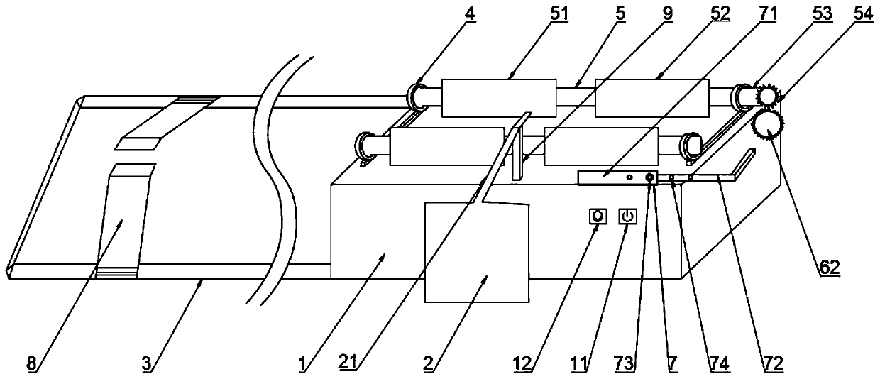
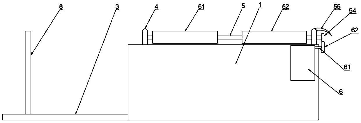
The invention relates to the technical field of machining, and particularly discloses a guide rail rotation device for a cutting machine. A base, the plasma cutting machine and a guide rail are included. Bearings, a supporting frame and a length adjusting pipe are arranged on the top of the base. The two bearings are arranged and arranged at the two ends of the top of the base correspondingly. Theouter rings of the bearings are fixed to the top of the base through iron rings. The inner ring of each bearing is provided with a wheel in a sleeving manner, wherein one end of the wheel penetratesthrough the bearing and is provided with a small gear on an extension part. The length adjusting pipe is arranged on the side edge of the top of the base and comprises an inner pipe, an outer pipe anda screw, wherein the inner pipe and the outer pipe are both provided with inserting holes. A motor is arranged in the base and connected with a big gear through a rotation shaft. A cutting handle ofthe plasma cutting machine is arranged on the supporting frame. The guide rail is arranged at the end, away from the small gear, of the base and is in sliding connection with a pipeline support. The guide rail rotation device is reasonable in structure and simple in operation, cut finished product pipe openings are free of deformation, and the cutting efficiency and precision can be improved.

Description

technical field [0001] The invention relates to the technical field of mechanical processing, in particular to a guide rail rotating device for a cutting machine. Background technique [0002] With the development of science and technology, the mechanical processing industry is developing more rapidly. Although the existing pipe cutting device can solve the separation of steel pipe segments, the cutting speed is relatively slow, and the technical requirements for engineers are relatively high. Some engineers are difficult to use. Precise cut. Therefore, the present invention provides a guide rail rotating device for a cutting machine, which can not only increase the cutting speed, but also improve the cutting accuracy. Contents of the invention [0003] Aiming at the above-mentioned shortcomings in the prior art, the present invention provides a guide rail rotating device for a cutting machine, which has a simple and reasonable structure and is convenient for popularizati...

Claims


Application Information

Patent Timeline
Patent Type & Authority Applications(China)
IPC IPC(8): B23K10/00B23K37/053B23K101/06
CPCB23K10/00B23K37/053B23K37/0538B23K2101/06
Inventor 薛旺
Owner 薛旺
Why Eureka
Try Eureka